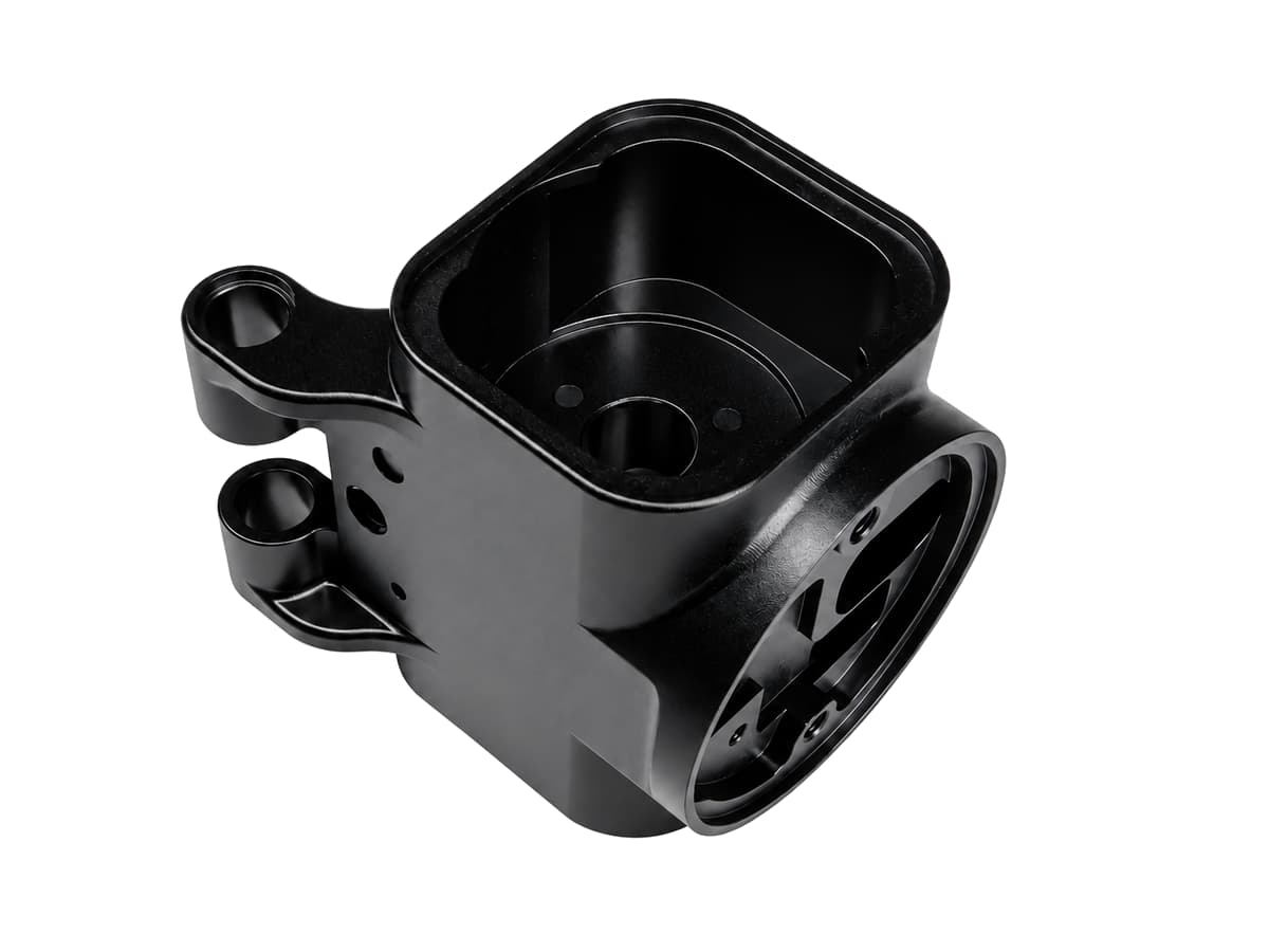
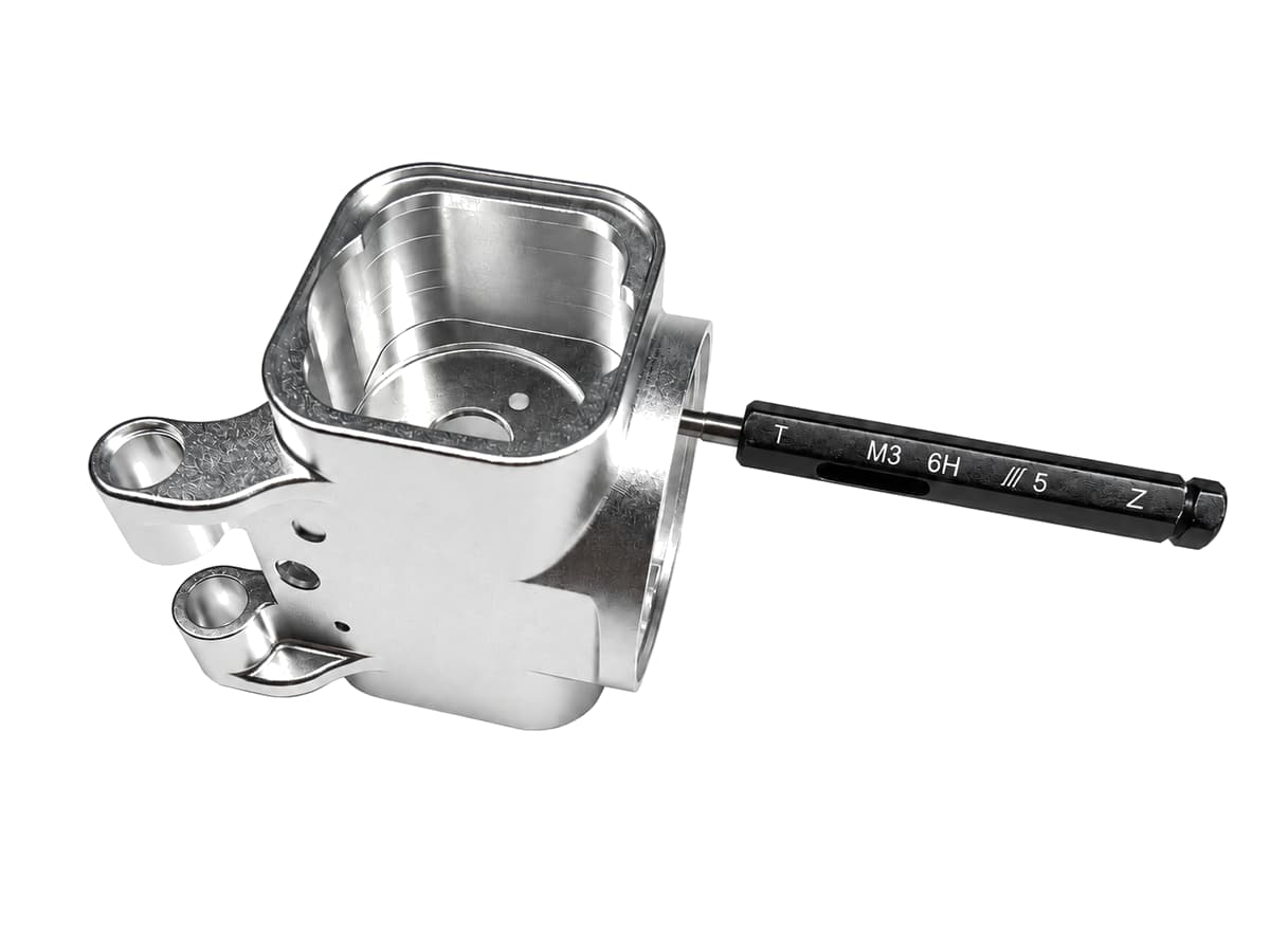
A screw that starts correctly can still bottom out before an assembly clamps. For CNC threaded holes, thread designation, usable engagement, hole depth and final inspection must describe the same intended joint.
Key takeaways
Separate full-thread depth from drilled depth and screw penetration.
Specify the thread system, size, pitch and internal tolerance class.
Check threads in the required final condition and inspect their location separately.
01
Define the thread before choosing a machining method
A threaded hole contains an internal helical thread that engages a mating fastener or component. Tapping is one way to produce it; thread milling is another. A drawing should define the required thread, while the manufacturing review establishes a suitable process unless a particular method is contractually required.
Specify the thread family, nominal size, pitch and internal tolerance class. Include handedness when it differs from the normal convention. A model showing a cylindrical opening is not sufficient evidence of the thread specification, particularly when files move between CAD systems.
02
Keep three different depths separate
For a blind hole, distinguish usable full-thread depth, the cylindrical drilled depth and the deepest point left by the drill. Tool lead geometry and clearance mean that these depths are not interchangeable. Define the depth reference clearly so the machinist and inspector interpret the drawing in the same way.
Screw penetration is a separate assembly calculation. Account for the clamped stack, washers, countersinks and screw length tolerance. A screw must generate the intended clamp load without contacting the hole bottom first. Do not use the overall drill depth as the available engagement length.
| Requirement | What it controls | Question to resolve |
|---|---|---|
| Full-thread depth | Usable internal thread | How much complete thread must be available? |
| Drilled cylindrical depth | Space for thread production | What tool lead and clearance are needed? |
| Maximum hole extent | Remaining wall or floor | Could the drill point break into another feature? |
| Screw penetration | Assembly clearance | Does the screw clamp before it bottoms out? |
03
Review engagement using the joint materials and loads
There is no single engagement length that validates every assembly. The internal material, fastener properties, load direction, repeated assembly and surrounding wall section all matter. A soft housing and a hardened steel fastener should not be assessed only by nominal thread diameter.
For a joint requiring repeated servicing, ask whether an insert is appropriate and define the exact insert system if selected. Its installation hole, local wall thickness and inspection requirements belong in the drawing package. Treat insert selection as an engineering decision rather than an unapproved substitution at quotation.
04
Give the process room to make a complete thread
Tapping requires a tool appropriate to the work material and hole type, with attention to chip evacuation in blind holes. Thread milling can be considered where tool access, diameter adjustment or the material makes it useful. Neither method removes the need to review the actual hole geometry.
Avoid specifying a universal extra-depth allowance for every blind hole. Ask the supplier to verify the selected tool's clearance against the available floor thickness. If a hole intersects a passage, mark the intersection and discuss burr removal and cleaning access before release.
- Check entry chamfer against the usable thread requirement.
- Keep the tool approach clear of adjacent walls and bosses.
- Identify cross-holes, thin floors and prohibited breakthrough.
- Define cleanliness requirements for internal passages.
05
Inspect the finished thread and its location
Agree the applicable thread-gauging method, gauge class and acceptance procedure. A matching GO/NO-GO plug gauge can support thread acceptance, but it does not by itself establish hole position, perpendicularity or all assembly requirements. Those characteristics need separate drawing controls and suitable measurements.
State whether acceptance occurs after coating or other finishing. Do not assume a thread that passes before finishing will meet the final requirement. Identify masking or process allowances during review, and do not permit thread chasing after coating without considering the resulting loss of coating protection.
06
Use an assembly scenario to expose missing information
Suppose a cover is secured to a blind-threaded housing. The quotation package lists the thread size but omits full-thread depth and the cover stack. One supplier may assume a shallow engagement while another allows a deeper hole. Both quotations can look comparable even though they describe different assemblies.
Resolve the difference by releasing the mating screw specification, controlled cover thickness, usable thread depth and maximum hole extent. Request a first-piece assembly check where appropriate, alongside the specified gauging and dimensional records. Document assumptions before comparing price and delivery.
- Controlled CAD and drawing with thread callouts
- Material condition and quantities
- Full-thread depth, maximum drilling depth and entry details
- Finishing, masking, deburring and cleaning requirements
- Thread gauges, depth verification and positional inspection scope
07
Technical references and further reading
This original guide expands the threaded-hole topic into a drawing and purchasing checklist. Use toolmaker guidance for process selection and the project specification for acceptance.
Frequently asked questions
Questions engineers and buyers ask before quotation.
Is tapped depth the same as drill depth?+
No. Usable full-thread depth excludes incomplete thread and tool-clearance regions. The drawing should distinguish full thread, cylindrical drilling depth and maximum hole extent.
Can a thread plug gauge verify hole position?+
No. Thread gauging and positional inspection address different requirements. Specify both when the joint needs controlled thread size and location.
Should every internal thread be tapped?+
No. Tapping and thread milling are possible routes. Material, hole geometry, access, quantity and the required thread determine the suitable process.

Julie Cai
Project contact connecting international customers with MIM Machining's manufacturing and engineering review team.
Contact Julie