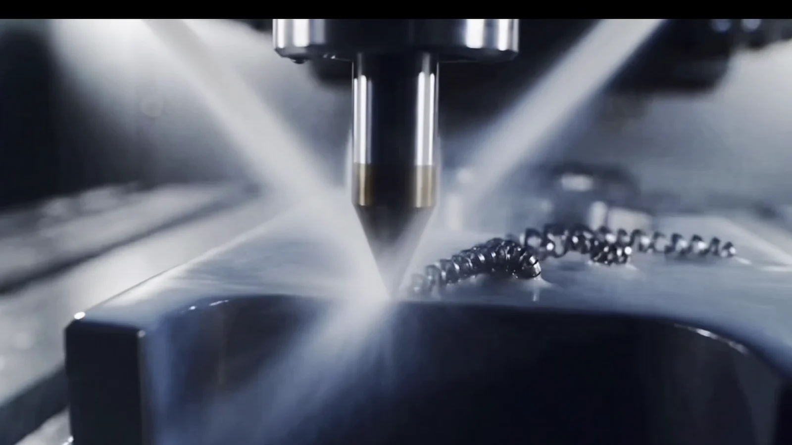
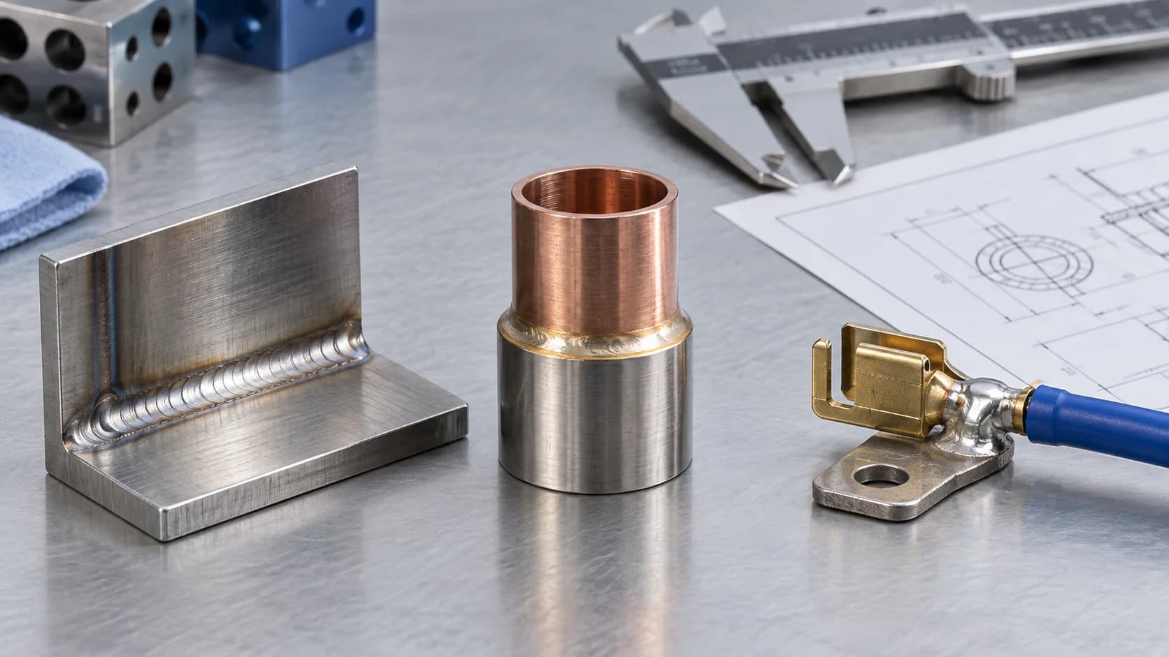
The best joining process is the one that protects the assembly's load path, materials, dimensions, sealing requirements and production plan—not simply the one with the highest temperature.
Key takeaways
Choose the joining route from service loads, base-metal compatibility, heat sensitivity, sealing needs and inspection—not temperature alone.
Welding melts the base material locally; brazing and soldering use a filler metal without intentionally melting the parent components.
A useful assembly RFQ identifies joint geometry, materials, finish, critical dimensions, leak or electrical requirements and acceptance tests.
01
The practical difference between welding, brazing and soldering
Welding creates a joint by locally melting and fusing the base materials, with or without filler metal. It is commonly considered when the joint is part of the structural load path or when a continuous fused seam is required. Heat input, joint access, weld sequence and restraint all affect distortion and the final dimensions of a precision assembly.
Brazing and soldering melt a filler metal that flows between prepared components while the base materials remain solid. Brazing uses a higher-temperature filler system and is generally selected for stronger mechanical or sealed joints; soldering uses lower process temperatures and is common for electrical connections and heat-sensitive assemblies. The correct filler, flux or atmosphere must be compatible with the materials and service environment.
- Welding: fused base material and concentrated heat input
- Brazing: capillary filler-metal joint for compatible, closely fitted surfaces
- Soldering: lower-temperature filler-metal joint, often for electrical or light-duty connections
02
Use the load path and failure mode to screen the options
Begin with what the joint must survive. A bracket carrying cyclic mechanical load is a different problem from a copper tube joint that must remain leak-tight or a terminal that must maintain electrical continuity. Define static load, vibration, pressure, temperature cycling, corrosion exposure and intended service life before selecting a process.
Joint strength cannot be predicted from the process name alone. Base materials, filler selection, joint area, gap, surface preparation, heat cycle and operator or equipment control all influence performance. Prototype coupons or representative assemblies may be appropriate when the joint is safety-critical or the material combination is unfamiliar.
- Structural load and fatigue direction
- Pressure, vacuum or leak-tightness requirement
- Electrical and thermal conductivity
- Operating temperature and corrosion environment
- Repairability and expected service life
03
Compare material compatibility and heat sensitivity
Welding is usually most straightforward when the parent metals have compatible metallurgy and the assembly can tolerate a localized melt zone. Dissimilar metals, thin walls, plated parts and heat-treated components may require a different joining strategy or a carefully qualified procedure.
Brazing can connect some dissimilar-metal combinations and distribute load over an overlapping joint, but clearances, surface cleanliness and filler flow are critical. Soldering limits thermal exposure further, yet its lower service temperature and mechanical capability must fit the application. Coatings, heat treatment, hardness and cosmetic finish should be reviewed as part of the joining sequence rather than after it.
- Exact alloy and material condition
- Thickness difference between joined components
- Plating, coating or oxide layer
- Heat-treatment and hardness requirements
- Galvanic or chemical compatibility in service
04
Control distortion, appearance and downstream dimensions
Precision assemblies often fail at the drawing level before they fail mechanically. Welding heat can move holes, twist thin sheet, pull mounting faces or change the relationship between machined features. A practical plan may use tabs, fixtures, balanced weld sequencing, intermittent welds where permitted, or machining after joining.
Brazing heats a wider joint region and may reduce local melting, but the complete assembly still experiences a thermal cycle. Soldering generally introduces less heat, although poor fixturing can still shift small components. Define which dimensions apply before joining, after joining and after any final machining or finishing operation.
- Post-join flatness and hole position
- Maximum permitted cosmetic discoloration
- No-spatter and no-filler zones
- Machining allowance after joining
- Finish and cleaning sequence
05
Design the joint for the selected process
A welded butt or fillet joint needs torch access, a clear weld callout and enough local stiffness to manage heat. A brazed joint normally benefits from controlled overlap and capillary clearance. A soldered terminal needs clean, wettable surfaces, adequate contact area and strain relief so the electrical joint does not carry unintended mechanical load.
Do not use a generic note such as 'join securely' when the joint controls performance. The drawing should define joint location, extent, size or overlap, acceptable appearance and any prohibited regions. If the supplier is expected to recommend the process, state the functional requirements and allow the recommendation to be reviewed before production.
- Joint type, length, overlap and accessible sides
- Permitted filler or approved material system
- Critical surfaces that must remain free of filler or spatter
- Fixture datums and final assembly dimensions
- Cleaning, passivation, plating or coating after joining
06
Plan inspection around the real risk
Visual inspection can confirm continuity, obvious cracks, incomplete fill, excess solder, contamination and general workmanship, but appearance alone does not prove internal integrity. The inspection method should match the failure mode and may include dimensional checks, leak or pressure testing, electrical resistance, destructive coupons or an agreed nondestructive examination method.
Specify the applicable workmanship standard, acceptance criteria, sampling plan and documentation during quotation. If a qualified procedure, operator qualification, material certificate or special-process record is required, identify it before the supplier chooses equipment and estimates cost.
- Visual and dimensional acceptance criteria
- Leak, pressure or flow test
- Electrical continuity or resistance
- Sectioned coupon, pull test or other destructive validation
- Required procedure, personnel and lot records
07
Prepare a quote-ready metal assembly RFQ
Send the assembly model, controlled drawings and bill of materials together. Include the exact alloys, thicknesses, quantities, joint callouts, critical post-join dimensions, finish, service conditions and inspection requirements. Mating-part context helps the manufacturing team understand which surfaces control fit and function.
MIM Machining can review drawing-led sheet metal and precision component assemblies. Available joining processes, qualifications and acceptance methods must be confirmed for the specific project. Upload the current file package so manufacturing, joining, finishing and inspection can be evaluated as one route.
- Assembly CAD, component drawings and current revisions
- Bill of materials with exact alloy and condition
- Expected prototype and production quantities
- Joint loads, pressure, temperature and corrosion exposure
- Final dimensions, appearance zones and finish
- Inspection, documentation, packaging and delivery requirements

Julie Cai
Project contact connecting international customers with MIM Machining's manufacturing and engineering review team.
Contact Julie