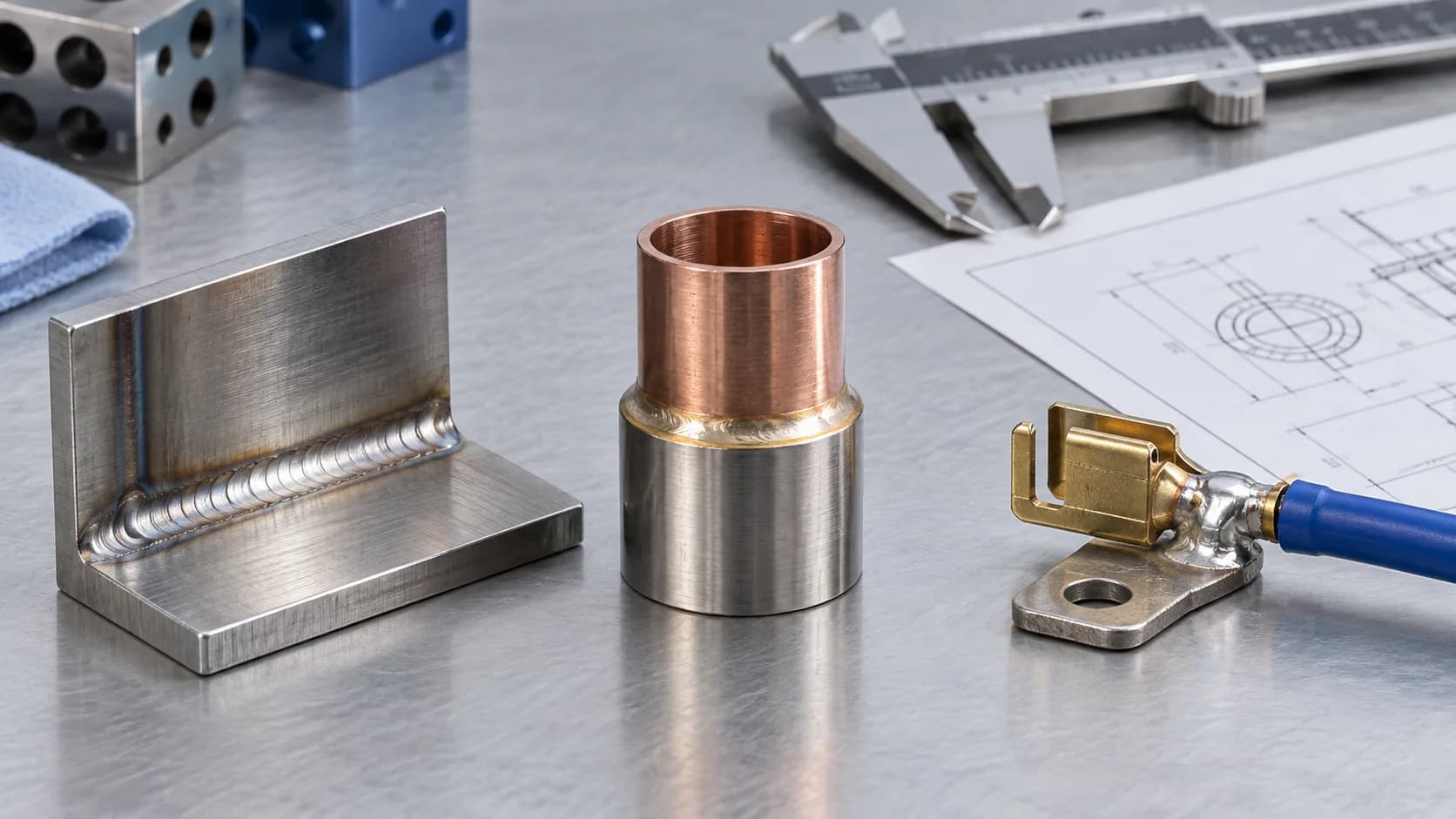
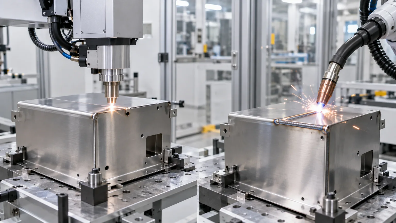
Laser and MIG welding can both produce sound metal assemblies, but they solve different production problems. The best choice begins with joint geometry, fit-up, material, distortion risk and the acceptance plan.
Key takeaways
Laser welding concentrates heat into a narrow zone and can support precise, low-distortion seams when joint fit-up and access are well controlled.
MIG welding is versatile for a wider range of joint gaps and material thicknesses, but filler, spatter, heat input and post-weld cleanup must be considered.
The RFQ should define materials, thicknesses, joint drawings, cosmetic zones, final dimensions, production quantity and inspection requirements before a process is selected.
01
How laser welding and MIG welding create the joint
Laser welding uses a focused energy source to melt a narrow region along the joint. The concentrated heat can produce a small heat-affected zone and a clean seam, which is useful when surrounding dimensions and appearance are sensitive. The process depends on stable joint location, controlled fit-up and suitable access for the beam and shielding arrangement.
MIG welding feeds a consumable wire electrode through the torch while shielding gas protects the weld pool. The filler wire helps bridge practical joint variation and makes the process adaptable to many sheet, plate and fabricated assembly applications. Torch angle, travel speed, wire selection, gas, heat input and welding sequence all influence the result.
- Laser welding: concentrated heat, narrow seam and demanding joint alignment
- MIG welding: continuously fed filler wire, broad material use and greater tolerance for practical fabrication variation
- Neither process is automatically better; the assembly drawing and production conditions decide
02
Compare heat input, distortion and final dimensions
Thin sheet assemblies can move as the joint heats and cools. A concentrated laser process may reduce the width of the heat-affected zone and limit visible distortion, but only when the joint is located consistently and the energy is delivered to the intended interface. Reflective materials, coatings and changing gaps can alter the process window.
MIG welding typically introduces heat across a larger area and adds filler metal. Fixtures, tack sequence, balanced welding and post-weld machining may be needed to protect flatness, hole position or sealing faces. The drawing should distinguish dimensions that apply before welding from those that must be achieved on the completed assembly.
- Flatness and angular distortion after joining
- Movement of mounting holes and machined interfaces
- Heat-sensitive coatings, hardness or cosmetic surfaces
- Allowance for post-weld machining or straightening
03
Use material, thickness and fit-up to screen the process
Material grade and thickness affect energy absorption, penetration, filler selection and crack sensitivity. A joint that works in mild steel may require a different route in stainless steel or aluminum. Exact alloy, temper, coating and service environment should therefore be part of the quotation package.
Fit-up is especially important for precision laser welding. The process is less forgiving when gaps, edge mismatch or part location vary. MIG welding can accommodate a wider range of gaps through filler addition, although excess variation still changes bead shape, heat input and final dimensions. A supplier should review actual tolerance stack-up rather than an ideal CAD interface alone.
- Base-metal grade, thickness and condition
- Joint gap, edge mismatch and accessible sides
- Need for filler metal and acceptable bead profile
- Coating, plating or oxide layer near the weld
- Corrosion, temperature and fatigue exposure in service
04
Evaluate speed, automation and production quantity
Laser welding can be attractive for repeatable assemblies where fixtures hold the joint consistently and the seam can be followed at production speed. Equipment, guarding, programming and process development add fixed cost, so the economics improve when the geometry and quantity justify that preparation.
MIG welding is widely available and can support prototypes, mixed fabrication work and production assemblies. Manual, mechanized and robotic routes have different repeatability and setup economics. Compare the complete route—including fixturing, filler, cleanup, inspection and any post-weld machining—rather than comparing arc time alone.
- Prototype versus recurring production quantity
- Fixture complexity and changeover frequency
- Manual, mechanized or robotic access
- Spatter removal, grinding and cosmetic finishing
- Inspection time and rework exposure
05
Plan weld quality and inspection around the failure risk
A visually smooth seam does not prove penetration, fusion or fatigue performance. Inspection should address the actual risk: dimensional shift, surface discontinuity, leak path, insufficient penetration, porosity or cracking. Acceptance criteria need to be agreed before production so the welding route and sample plan can be designed accordingly.
Depending on the project, the plan may include visual and dimensional inspection, leak testing, sectioned samples, destructive testing or a specified nondestructive examination method. If a qualified procedure, operator record or lot documentation is required, identify it during quotation rather than after the first parts are welded.
- Required seam extent and bead acceptance
- Final assembly dimensions and fixture datums
- Leak, pressure or functional test
- Representative coupon or destructive validation
- Documentation, sampling and traceability expectations
06
Prepare a quote-ready welding RFQ
Send the assembly model, controlled component drawings and bill of materials together. Mark each joint, accessible side, final cosmetic surface and feature whose location must be protected after welding. Include prototype and production quantities so the supplier can compare manual, automated and fixture-intensive routes.
MIM Machining reviews drawing-led sheet metal fabrication and assembly projects. Welding methods, equipment, qualifications and inspection scope must be confirmed for the specific material and design. Share the current file package so cutting, forming, joining, finishing and dimensional control can be evaluated as one manufacturing plan.
- Assembly CAD, individual drawings and current revisions
- Exact alloys, thicknesses and material condition
- Joint callouts, accessible sides and prohibited weld zones
- Critical post-weld dimensions and cosmetic requirements
- Prototype quantity, production forecast and target timing
- Inspection, testing, documentation and finish requirements
Plan the next step
Continue from guide to project review.

Julie Cai
Project contact connecting international customers with MIM Machining's manufacturing and engineering review team.
Contact Julie