A bracket may look simple in CAD while its manufacturing route controls stiffness, hole position, cosmetic quality and total cost. This guide helps engineers compare CNC machining with cut-and-bent sheet metal before releasing drawings for quotation.
Key takeaways
Choose the process from load path, section geometry, functional datums, finishing and quantity rather than from bracket appearance alone.
Sheet metal suits constant-thickness parts built from cut and bent features; CNC machining suits three-dimensional sections, machined interfaces and features that depend on one rigid datum system.
Compare total delivered cost, including tooling, setups, forming variation, secondary machining, hardware, finishing and inspection.
01
Quick comparison: machined bracket or sheet metal bracket?
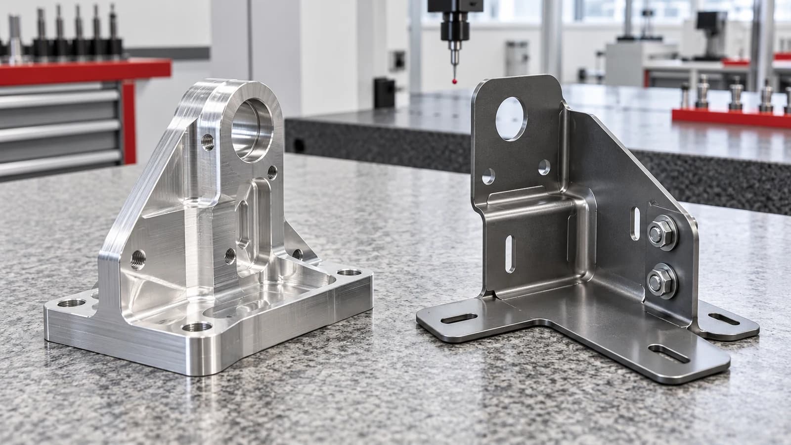
A sheet metal bracket begins as constant-thickness stock that is cut and formed. A CNC machined bracket begins as plate, bar, extrusion, casting or another blank and removes material to create the final geometry. Either route can produce a strong functional component, but they distribute material, tolerance and cost differently.
Use the comparison below to frame a DFM discussion. It does not replace structural analysis, material data or a project-specific manufacturing review.
| Decision factor | CNC machined bracket | Sheet metal bracket | What to confirm |
|---|---|---|---|
| Geometry | Three-dimensional pockets, bosses, variable thickness and machined interfaces | Constant thickness with cuts, bends, hems, louvers or formed details | Load path, envelope, access and mating geometry |
| Datum relationships | Critical faces and holes can often be machined in a coordinated setup | Bending can move features across bend lines; secondary machining may be needed | Functional datums and whether dimensions apply before or after forming |
| Stiffness | Local ribs and thick sections can be machined where required | Flanges, beads and returns create stiffness efficiently with less material | Load direction, deflection limit and fastener preload |
| Quantity | Low quantity can avoid dedicated forming tools but carries machining time | Repeat quantities can benefit from efficient cutting and forming | Prototype, pilot and annual release quantities |
| Surface and finish | Machined texture, deburring and anodizing or plating considerations | Tool marks, bend marks, welds, hardware and coating considerations | Cosmetic zones and final assembly exposure |
| Cost risk | Material removal, setups, tool reach and inspection | Flat-pattern yield, bends, tooling, welding, hardware and forming variation | Complete route and inspection scope |
02
Start with bracket function, load path and assembly
Define what the bracket supports and how the load enters and leaves the component. A mounting bracket may carry static weight, cyclic vibration, fastener preload, impact or thermal movement. The manufacturing process cannot compensate for an undefined service condition. Identify interfaces, fastener locations, allowable deflection, environment and any consequence of failure before optimizing cost.
Assembly context matters just as much as nominal strength. A thick bracket can still rock if its mounting pads are not coplanar, while a thin formed bracket can be very stiff when flanges and returns are aligned with the load. Provide mating-part geometry and required clearances so the DFM review can evaluate wrench access, head clearance, bend access and inspection access.
- Static, cyclic, shock and vibration loads
- Fastener size, preload, access and installation sequence
- Maximum permitted deflection at the supported feature
- Temperature, corrosion, cleaning and outdoor exposure
- Mating faces, keep-out zones and cable or hose clearance
- Safety factor and analysis requirements owned by the design team
03
Design sheet metal brackets around a controlled bend model
Sheet metal design should use a consistent material thickness, bend radius, bend allowance or K-factor and corner-relief rule. The flat pattern depends on the forming process and tooling, so a generic CAD default may not match the supplier's validated bend data. Share the folded model and drawing; use the flat pattern as supporting information unless the manufacturing agreement makes it controlling.
Features near a bend can stretch, distort or shift during forming. Hole-to-bend distance, flange length, relief geometry and tool access should be reviewed against material, thickness and selected tooling. Place critical holes after forming through secondary machining only when the functional requirement justifies the added setup and cost.
- Material grade, thickness and temper or condition
- Inside bend radius and permitted process variation
- Bend direction, sequence and tool access
- Corner and bend relief geometry
- Critical holes or slots crossing bend zones
- Dimensions that apply in the formed state
04
Use formed features to improve stiffness without excess mass
A flat sheet can gain substantial stiffness from flanges, returns, hems, beads or boxed sections. These features move material away from the neutral axis and can be more mass-efficient than simply increasing thickness. Their benefit depends on direction, length, corner continuity and connection to the load path.
Every formed feature also changes manufacturing. Small returns may conflict with press-brake tooling, closed sections may require welding or multiple pieces, and closely spaced bends can restrict access. Review stiffness and fabrication together so a feature added for strength does not create an impossible bend sequence or unnecessary joining operation.
05
Choose CNC machined brackets for integrated three-dimensional features
CNC machined brackets are strong candidates when the part needs bosses, bearing seats, counterbores, deep pockets, variable thickness, angled interfaces or critical faces linked in one datum system. Custom CNC parts can also combine locating and mounting functions that would otherwise require several fabricated pieces and welds.
Machining cost rises with removed volume, setup count, tool reach, small internal radii and unnecessary surface requirements. Design a near-net section where practical, retain accessible internal radii and avoid making every face cosmetic or tightly toleranced. An extrusion or casting followed by precision machining may be worth evaluating for repeat demand, but tooling economics and material properties must be reviewed separately.
- Machined pads, bores and bearing or seal interfaces
- Compound angles or multi-face feature relationships
- Variable wall thickness and local reinforced sections
- Integrated locating pins, shoulders or cable passages
- Low quantity where forming or casting tools are difficult to justify
- Parts needing documented precision CNC machining inspection
06
Control holes, fasteners and hardware in the correct process state
Bracket drawings should distinguish holes cut before forming from holes whose final position matters after forming. A hole can be accurate in the flat pattern and still shift relative to a mounting face after bending. For critical assemblies, dimension from functional formed datums and agree whether the supplier will form, ream, machine or gauge the feature in its final state.
Threaded requirements also affect the route. Machined brackets can use tapped holes, thread inserts or through-fasteners. Sheet metal brackets may use formed threads, weld nuts, self-clinching hardware, rivet nuts or separate backing components. Specify the approved hardware, installation direction, torque or push-out requirement where relevant, and keep hardware clear of bend tooling and edge conditions.
07
Apply tolerances to function, not to the entire bracket
A bracket drawing should identify the interfaces that control assembly and allow practical variation elsewhere. Applying a tight profile or positional requirement to the entire formed envelope can create inspection and cost without improving function. Conversely, leaving mounting pads, hole patterns or bearing interfaces under a broad general tolerance may create assembly risk.
Define the datum reference frame from stable functional surfaces. State whether flatness, parallelism or position applies before or after coating, welding, forming or stress relief. For flexible sheet metal, the inspection state and support condition may need definition. For machined brackets, consider how clamping and material removal can affect thin sections after release.
08
Compare material, corrosion protection and cosmetic requirements
Material selection must account for strength, stiffness, corrosion, temperature, joining and finishing. Aluminum can reduce mass and accept several protective or cosmetic finishes, while stainless steel may reduce coating needs in some environments but changes cutting, forming and joining behavior. Carbon steel can be economical when coating and corrosion control are properly specified.
Finishing should be planned with the manufacturing route. Anodizing, conversion coating, passivation, plating, powder coating and painting have different effects on dimensions, threads, electrical contact and appearance. Define masking, grounding, rack-contact and no-coating zones. A welded sheet metal assembly may need cleanup before coating, while a machined bracket may require protected datum faces or threads.
09
Evaluate total delivered cost across real quantity breaks
Do not compare a machining cycle with a bend operation in isolation. CNC machining cost includes stock, programming, setups, cutting time, tool wear, deburring and inspection. Sheet metal cost includes flat-pattern programming, material yield, cutting, forming, hardware, welding, cleanup, finishing and inspection. Dedicated fixtures or forming tools may change the economics at repeat volume.
Ask for prototype, pilot and production quantity breaks that match the purchasing plan. A machined bracket can be attractive while the design is changing because it avoids dedicated tooling. A cut-and-bent route can become more economical after geometry stabilizes. A hybrid route may machine only the critical interface after forming or join a machined insert to a fabricated structure.
- Prototype and design-verification quantity
- Pilot build and expected annual demand
- One-time programming, tooling and fixture cost
- Recurring material, cycle, hardware and inspection cost
- Secondary machining, welding and finishing
- Revision risk, maintenance and spare-part strategy
10
Build an inspection plan around bracket assembly risk
Inspection should protect the assembly interfaces: mounting-hole position, pad flatness, included angle, profile, bore alignment, hardware installation and cosmetic zones as applicable. Select measurement methods that suit the feature and production quantity. A CMM may document multi-face relationships, while dedicated gauges, height gauges, optical systems or an assembly fixture may be more efficient for other characteristics.
For formed brackets, record whether the part is measured free, supported or restrained. For welded assemblies, identify final dimensions after joining. For finished parts, decide which dimensions require pre-finish process control and which require final verification. Put the report and sampling requirements in the RFQ so suppliers quote the same quality scope.
11
Prepare a quote-ready bracket RFQ
Send the STEP model and controlled drawing with exact material, thickness or stock form, quantities, finish and inspection requirements. Include mating-part context and identify the load-bearing or alignment features. If both processes are acceptable, state the functional requirements and ask the supplier to compare routes rather than prescribing an unsupported process.
MIM Machining reviews CNC machined brackets and drawing-led sheet metal fabrication projects. The selected route, available equipment, tooling, finishing and inspection scope are confirmed for the actual geometry and requirements. A complete RFQ helps separate process choice from assumptions that can distort price or lead time.
- STEP model, controlled drawing and current revision
- Material grade, condition, thickness or starting stock
- Functional datums, critical dimensions and surface requirements
- Fasteners, inserts, welding and assembly responsibilities
- Prototype, pilot and production quantity breaks
- Finish, cosmetic zones, masking and packaging
- Inspection reports, testing, traceability and delivery destination
12
Technical references
These resources support the design and measurement framework. The released drawing, verified material data and supplier-specific tooling rules remain controlling for each project.
13
Send your bracket drawing for process review
Send the bracket model, drawing, load and mating context, quantities, finish and inspection expectations. MIMCNC can review CNC machining, sheet metal fabrication or a hybrid route against the actual component requirements.
Use the inquiry page or contact Julie Cai at juliecai@mimcnc.com and +86 136 7015 0900. Manufacturing feasibility and project scope are confirmed before quotation.
Frequently asked questions
Questions engineers and buyers ask before quotation.
Are CNC machined brackets stronger than sheet metal brackets?+
Not automatically. Strength and stiffness depend on material, section geometry, load direction, fasteners, bends, welds and interfaces. A formed bracket with well-placed flanges can be very efficient, while a machined bracket can place material and precision interfaces in three dimensions.
When should a bracket be CNC machined?+
CNC machining is worth evaluating for integrated bosses, bores, pockets, variable thickness, compound angles, precision mounting pads or low quantities that do not justify dedicated forming tools. Total cost still depends on stock, setups, removed volume and inspection.
When is sheet metal better for a bracket?+
Sheet metal is often suitable when the part can use constant-thickness stock, cut profiles and practical bends, especially when flanges or returns provide the needed stiffness. Quantity, tooling, welding, hardware, finishing and formed tolerance must be considered together.
Should critical holes be made before or after bending?+
It depends on the required final relationship. Holes can be cut efficiently in the flat, but bending may move them relative to a functional face. Critical features may need formed-state dimensioning, gauging or secondary machining when the assembly requirement justifies it.
How can bracket manufacturing cost be reduced?+
Use functional tolerances, accessible features, practical radii, standard materials and hardware, realistic quantity breaks and a finish suited to the environment. Compare the complete machining or fabrication route rather than one operation.
What should be included in a bracket RFQ?+
Provide the STEP model, controlled drawing, material and condition, thickness or stock form, quantities, fasteners, joining, finish, cosmetic zones, critical datums and dimensions, inspection requirements, delivery destination and functional context.
Plan the next step
Continue from guide to project review.

Julie Cai
Project contact connecting international customers with MIM Machining's manufacturing and engineering review team.
Contact Julie