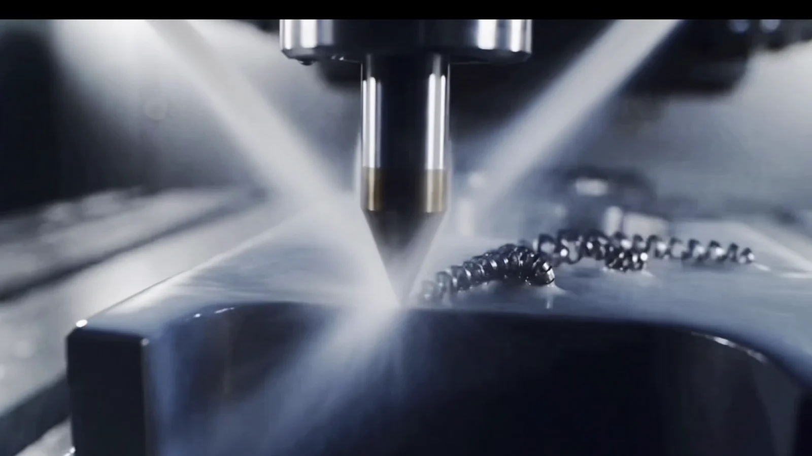

A buyer-focused DFM guide to controlling CNC machining cost while protecting the dimensions, surfaces and material properties that make the part work.
Key takeaways
Protect functional requirements first, then remove complexity that does not improve part performance.
Selective tolerances, accessible geometry and fewer setups can reduce both machining and inspection effort.
A complete RFQ helps suppliers quote the intended process instead of pricing uncertainty.
01
Begin with function, not the lowest unit price
Cost reduction starts by separating what the component must do from what is simply present in the current design. Bearing fits, sealing faces, alignment features, threads and mating interfaces may deserve tight control. Non-functional surfaces often do not need the same tolerance or finish.
The goal is to preserve the requirements that protect assembly and service performance while removing specifications that add machining, setup or inspection work without adding value.
- Identify critical-to-function features
- Mark mating and sealing surfaces
- Separate cosmetic expectations from dimensional requirements
- Confirm which dimensions require recorded inspection
02
Improve tool access and simplify difficult geometry
Cutting tools need room to enter, remove material and evacuate chips. Deep narrow pockets, tall thin walls, sharp internal corners and features hidden behind other geometry can require smaller tools, slower passes or additional orientations.
Review whether an internal corner can accept a larger radius, whether a pocket can be made shallower, or whether a feature can be opened to improve access. For thin or flexible sections, discuss stability before freezing the design.
- Use practical internal radii
- Avoid unnecessary deep narrow cavities
- Provide clearance around holes, slots and threads
- Discuss thin walls before freezing the design
03
Apply tolerances and surface finish selectively
A blanket tight tolerance forces manufacturing and quality teams to treat every dimension as critical. That can increase tool compensation, process checks and final inspection even when only a few features control function.
Use a general tolerance for non-critical geometry and assign specific dimensional or geometric controls to functional features. Surface roughness should follow the same logic: sealing, bearing and sliding interfaces may need special attention, while hidden clearance faces may not.
- Build a functional datum scheme
- Call out only the relationships that matter
- Specify finish by application
- Account for coating or heat-treatment effects
04
Match the process route to geometry and volume
A part that looks simple may still require several setups if features are located on many faces. Conversely, a more capable machine can sometimes consolidate operations when positional relationships justify it. The best route depends on geometry, workholding, tolerance relationships, quantity and repeat demand.
Share prototype quantity and expected production volume. A supplier may choose flexible workholding for early samples and a more dedicated approach for repeat orders. Stable revision control also prevents setup work from being repeated after avoidable design changes.
- Compare three-axis, indexed and five-axis routes
- Consider turning or turn-milling for rotational parts
- Provide quantity breaks and annual demand
- Keep revisions controlled
05
Choose materials and finishes with the whole requirement in view
Material selection affects cutting behavior, tool wear, distortion risk and finishing. Specify the exact grade and condition when they are functionally required. If alternatives are possible, describe the mechanical, corrosion, thermal or regulatory properties that must be maintained.
Secondary finishes can change dimensions, appearance and masking requirements. Define coating type, cosmetic standard, protected threads and no-coat areas during quotation so the machining and finishing route can be planned together.
- State alloy, temper or heat-treatment condition
- Allow qualified alternatives only when appropriate
- Mark masking and no-finish zones
- Define appearance expectations with objective references
06
Send a quote-ready package
A complete package reduces assumptions that create risk allowances and clarification delays. Send the current 3D model with a controlled 2D drawing, then add material, quantity, finish, inspection documentation and target delivery context.
MIM Machining reviews drawing-led projects before production. Use the RFQ form to share the latest files and identify the features that must remain protected while DFM opportunities are evaluated.
- 3D CAD model and controlled 2D drawing
- Material grade and condition
- Prototype and production quantities
- Critical tolerances and finish requirements
- Inspection records and delivery expectations

Julie Cai
Project contact connecting international customers with MIM Machining's manufacturing and engineering review team.
Contact Julie