A practical look at how drawing review, process planning, controlled machining and dimensional inspection work together to turn a complex design into a reliable CNC machined part.
Key takeaways
A reliable precision part begins with a clear CAD model, controlled drawing and shared understanding of the features that protect function.
Process planning connects machine selection, workholding, tooling, datum control and in-process checks before cutting begins.
CMM inspection is most valuable when its results feed back into production control rather than acting only as a final sorting step.
01
Start with the design intent
A finished CNC machined component may look simple, but the work behind it rarely is. Complex geometry, feature relationships, material behavior, tool access and inspection requirements all influence how a design should be manufactured. The short MIM Machining video behind this guide shows the connection between engineering intent, CNC machining and dimensional inspection.
Before a machine program is created, the manufacturing team needs to understand what the part must do. A 3D CAD model describes the geometry, while the controlled 2D drawing should identify critical dimensions, datum references, material, surface finish, protected surfaces and reporting expectations. Reviewing these items early helps separate function-critical requirements from general dimensions and exposes unclear or difficult features before material and machine time are committed.
- Current 3D CAD model and controlled 2D drawing
- Critical dimensions, tolerances and datum references
- Material specification and required condition
- Surface finish, threads, bores and mating features
- Inspection and reporting expectations
02
Build the manufacturing plan around the part
Once the design intent is clear, the team can decide how the component should be made. The manufacturing plan may consider machine type, workholding, cutting tools, setup sequence, datum transfer and intermediate inspection. The goal is not simply to remove material; it is to protect the feature relationships that matter to part function.
A complex housing, for example, may include several faces, bores and mounting features that must relate accurately to one another. Repositioning the workpiece introduces additional workholding and alignment conditions. The team therefore evaluates whether a different setup strategy or multi-axis access can reduce handling while maintaining practical access to critical features. Thin walls, deep pockets and long-reach tools also need to be considered because they can affect rigidity and process stability.
03
Control the CNC machining process
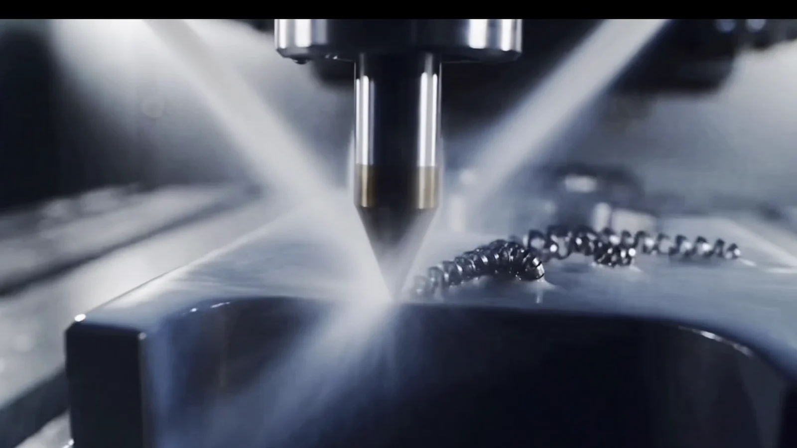
The cutting sequence shown in the video is the most visible part of the workflow: the tool, coolant, material removal and the emerging component. Reliable CNC machining, however, depends on controls around that operation. The correct material and drawing revision must be confirmed, the workholding and datum location must be verified, and the tooling and cutting parameters must fit the geometry and material.
For prototype work, the first parts provide useful feedback. The team can compare actual cutting conditions and measurement results with the original assumptions. Workholding, tool paths or inspection frequency can then be adjusted before production volume increases. This feedback helps the process remain repeatable from an approved sample through later orders.
- Verify material, drawing revision and workholding
- Select tooling appropriate to geometry and material
- Monitor tool condition and important process variables
- Use in-process checks where they reduce production risk
- Keep suspect or nonconforming parts clearly identified
04
Inspect the features that carry functional risk
The video also shows an operator using a coordinate measuring machine, or CMM, to inspect a manufactured component. CMM inspection is especially useful when a part contains complex geometry or when feature relationships cannot be verified efficiently with calipers, micrometers or gauges alone. Selected features can be measured relative to the defined datum structure so the inspection team can evaluate the drawing requirements.
That does not mean every dimension requires a full CMM report. The inspection plan should follow actual part risk. Critical bores, positional relationships, datum features and assembly interfaces may justify detailed verification, while simpler noncritical dimensions may be checked with conventional instruments. The reporting scope should be discussed during quotation so programming, fixturing, sampling and documentation can be planned with the manufacturing route.
05
Connect measurement results back to production
Inspection is most valuable when the results lead to action. If measurement data shows a trend near a tolerance limit, the team can review tool wear, workholding stability, thermal conditions or the machining sequence. This feedback loop helps prevent a small process shift from becoming a larger production problem.
For repeat orders, controlled records help the manufacturing team reproduce the approved process. The current drawing revision, process plan, inspection method and agreed reporting scope should remain connected to the correct part and order. This is the difference between treating inspection as a final sorting step and using it as part of process control.
06
Prepare a quote-ready CNC machining RFQ
A focused request for quotation gives the manufacturer enough information to evaluate feasibility, process and inspection needs. Send the native 3D model and latest controlled drawing, then add the project context that geometry alone cannot communicate. If a requirement is still under discussion, label it clearly instead of leaving the supplier to guess.
Early engineering communication often prevents unnecessary cost and reduces quotation revisions. Prototype quantity and expected production volume are both useful because the practical workholding, validation and inspection approach may change as demand develops.
- Material grade and required condition
- Prototype quantity and expected production volume
- Finish, coating or treatment requirements
- Critical tolerances and datum relationships
- Inspection reports and documentation expectations
- Target timing, destination and packaging needs
07
A reliable part comes from a connected workflow
Complex CNC machining is not defined by one dramatic cutting sequence. It is defined by how well the complete workflow connects design review, process planning, machining, inspection and feedback. The most useful supplier conversations begin with the part's function and risk rather than with a machine name alone.
If you are evaluating a complex CNC component, send MIM Machining the CAD model, drawing, material, quantity and inspection requirements. Our team can review the supplied information and respond with manufacturing feedback, lead-time considerations and a quotation based on the defined project scope.

Julie Cai
Project contact connecting international customers with MIM Machining's manufacturing and engineering review team.
Contact Julie