An engineering and sourcing overview of precision liquid cooling cold plates and quick-connect fittings, based on a project that progressed from prototypes to 100,000 shipped sets.
Key takeaways
Cold plates and quick-connect fittings should be reviewed as one liquid-cooling system, with flow, sealing and assembly interfaces defined together.
Scaling from prototypes to 100,000 shipped sets requires stable revisions, repeatable workholding, planned inspection and packaging that protects finished interfaces.
A quote-ready RFQ should define the coolant, pressure and leak criteria, critical interfaces, materials, finishes, quantities and documentation requirements.
01
Project snapshot: cold plates and quick-connect fittings
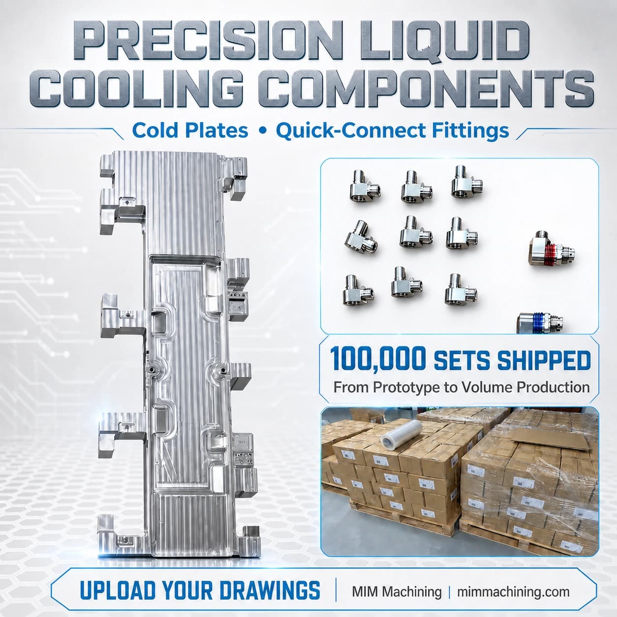
This liquid cooling component program combined precision cold plates with compact quick-connect fittings and progressed from prototype work to 100,000 sets shipped. The program shows why thermal hardware should be reviewed as an assembly: cold-plate geometry, ports, sealing interfaces and fittings must work together at production scale.
The project image records the product families and shipment milestone, but it does not replace a controlled drawing. Material grade, coolant, joining method, leak-rate limit, pressure, flatness, cleanliness and inspection documents remain project-specific and should be confirmed before quotation.
- Prototype-to-volume manufacturing path
- Cold plates and fittings reviewed as a coordinated set
- Production packaging planned around finished components
- Technical acceptance criteria controlled by the customer drawing
02
Review the complete liquid path
A liquid cooling assembly is only as reliable as the interfaces between its components. Channel geometry affects flow distribution and pressure drop, while ports and fittings establish how the cold plate connects to the wider cooling loop. Sealing surfaces, threads and orientation features must therefore be reviewed together rather than quoted as unrelated parts.
Buyers should identify the working fluid, operating temperature range, working pressure and any pressure-cycle expectations. Those inputs influence material compatibility, sealing choices, surface treatment and the test method. If the cooling loop includes customer-selected hoses, seals or mating connectors, their controlled specifications should be included in the RFQ.
- Coolant type and concentration
- Operating and test pressure
- Allowable pressure drop or flow target
- Seal and mating-connector specification
- Temperature and service environment
03
Cold-plate features that influence manufacturing
Cold plates commonly combine a thermal contact surface, internal flow paths, ports, mounting features and sealing or joining interfaces. Flatness and surface finish may matter where the plate contacts a heat source, but applying the same tight requirement to every surface can add machining and inspection cost without improving thermal performance.
Internal channels also need practical tool access, radii, wall thickness and deburring provisions. When a design uses a separate cover or another joining process, the manufacturing plan should account for distortion, final machining, cleanliness and leak testing. The correct route depends on the actual geometry and acceptance criteria rather than on a generic cold-plate specification.
- Thermal contact flatness and roughness
- Channel depth, width, radii and wall thickness
- Port location and thread or sealing details
- Joining and post-joining distortion risk
- Cleaning and leak-test requirements
04
Quick-connect fittings need controlled interfaces
Compact liquid cooling fittings can contain several critical relationships within a small envelope. Thread form, sealing grooves, shoulder positions, concentric diameters and angular outlets may all affect assembly. A visually similar fitting is not automatically interchangeable when seal compression or mating depth changes.
The RFQ should include the mating connector, seal specification and any orientation requirement. Materials and finishes should be selected for coolant compatibility and the service environment. If colored identification rings, protective caps or special packaging are required, define them as controlled product requirements rather than leaving them to production interpretation.
- Thread and port standard
- Seal groove and shoulder geometry
- Mating depth and orientation
- Material and surface treatment
- Identification and packaging requirements
05
What changes when production reaches 100,000 sets
A prototype proves that the geometry can be manufactured; volume production requires the process to remain stable across repeated lots. Drawing revisions, fixtures, tool life, in-process checks and final acceptance criteria need to be planned before quantities increase. Changes that appear minor during prototyping can affect interchangeability when thousands of assemblies are involved.
Inspection should focus on characteristics that protect flow, sealing, thermal contact and assembly. The customer and supplier should agree which features require recorded results, how often they are checked and what lot identification is needed. Packaging also becomes part of process control because threads, sealing faces and cosmetic surfaces must arrive protected and clean.
- Freeze the approved drawing and revision
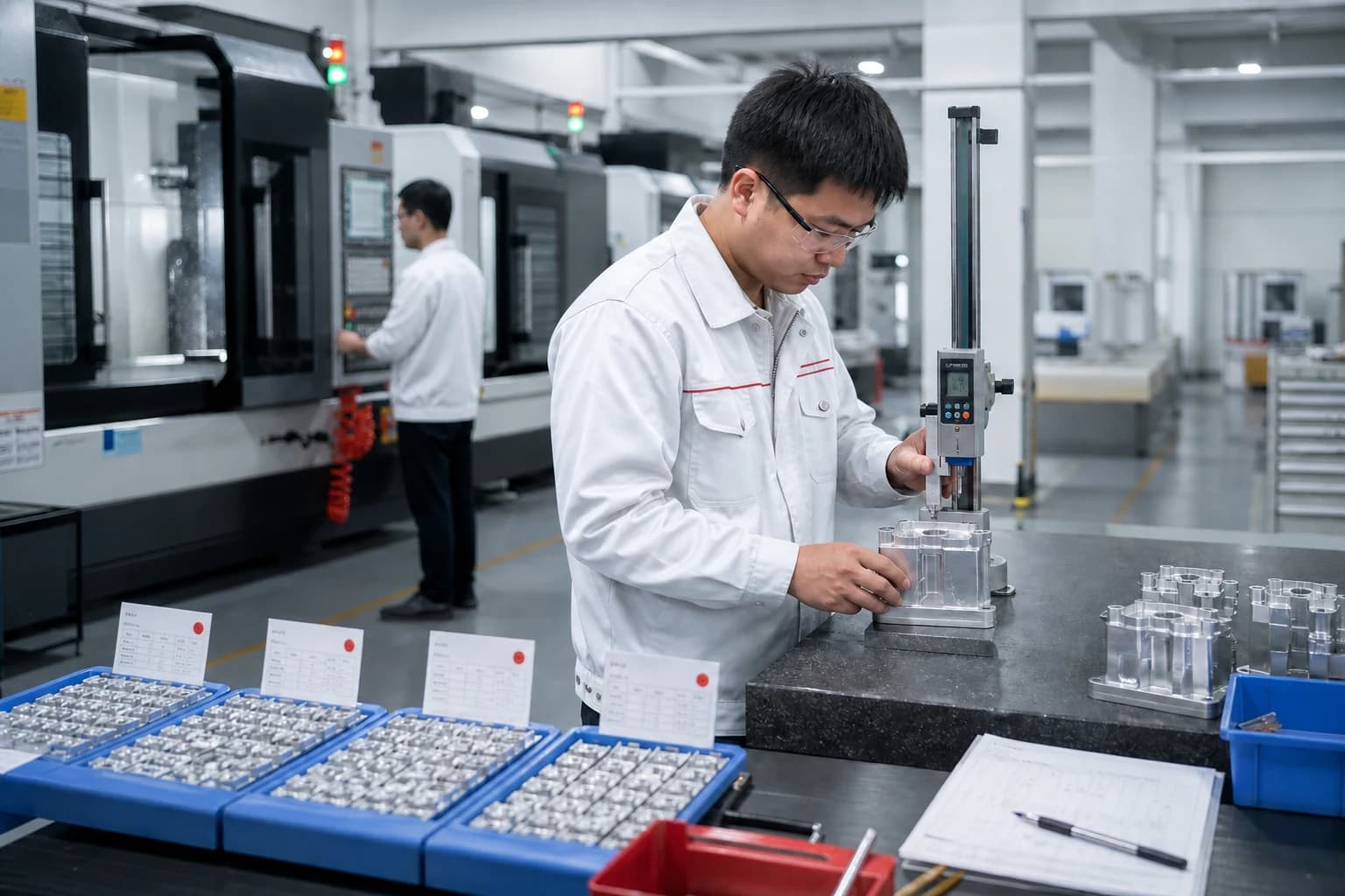
- Use repeatable workholding and process controls
- Define critical-characteristic sampling
- Control lot identification and records
- Protect threads and sealing faces during shipment
06
Build a quote-ready liquid cooling component RFQ
Send the current 3D models and controlled 2D drawings for both the cold plate and fittings. Add the operating context that cannot be understood from geometry alone, including coolant, pressure, leak criteria, thermal interface requirements, materials, finishes, prototype quantity and expected production demand.
MIM Machining reviews drawing-led liquid cooling projects from prototype planning through repeat production. Upload the current files and highlight the characteristics that control sealing, flow, thermal contact and assembly so the manufacturing and inspection route can be evaluated together.
- 3D CAD files and controlled drawings
- Coolant and temperature range
- Working pressure, test pressure and leak-rate limit
- Critical flatness, roughness and sealing interfaces
- Material, finish and cleanliness requirements
- Prototype quantity, volume forecast and delivery plan
- Inspection reports, traceability and packaging expectations

Julie Cai
Project contact connecting international customers with MIM Machining's manufacturing and engineering review team.
Contact Julie