A large metal component does not automatically belong on the largest available machine. Some designs need a rigid machined body with controlled bores and datums; others are more practical as cut, formed and joined sheet-metal assemblies. This guide helps engineering and sourcing teams choose the route from the drawing instead of from part size alone.
Key takeaways
Choose CNC machining when functional datums, precision bores, thick sections or complex solid geometry dominate the design.
Choose sheet metal fabrication when the part is mainly a shell, frame, guard, enclosure or structure that can be built from cut and formed stock.
For many large assemblies, the lowest-risk route combines fabricated structure with local CNC-machined interfaces rather than forcing the entire part into one process.
01
Start with the part structure, not only its overall size
The longest dimension is only the first screening question. Two parts with the same external envelope can require completely different manufacturing routes. A solid housing with bearing bores, sealing faces and related datum features behaves very differently from an enclosure made from panels, bends and welded joints.
Before selecting a process, separate the design into functional interfaces and structural volume. Ask which surfaces locate the assembly, which features carry load, which dimensions control alignment, and how much of the remaining material is present only to create a shell or support those interfaces. This distinction usually reveals whether material removal, fabrication or a hybrid route is the better starting point.
02
When large-part CNC machining is the better fit
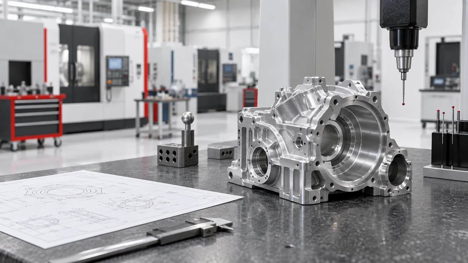
CNC machining creates geometry by removing material from plate, billet, casting, forging or a pre-fabricated blank. It is a strong option when the component depends on continuous material, stable datum relationships and accurately located features across several faces.
Large-part machining is not confirmed from nominal machine travel alone. The engineering review must also consider raw stock size and weight, fixture space, cutter approach, spindle clearance, lifting, repositioning, material condition and the planned inspection method.
- Thick plates, bases and housings with deep pockets or stiff ribs
- Bearing seats, precision bores, sealing faces and aligned hole patterns
- Parts where welded joints would interfere with stiffness, sealing or datum continuity
- Low- or moderate-volume parts whose geometry can be reached and inspected in a controlled setup plan
- Components that need coordinated milling, boring, drilling, grinding or secondary finishing
03
When sheet metal fabrication is the better fit
Sheet metal fabrication builds volume from relatively thin stock through cutting, bending, rolling, joining, hardware installation and finishing. It is often more material-efficient than machining a large open structure from a solid block.
The process is especially suitable when a design can be divided into manufacturable panels, channels, brackets or frames without compromising its functional load path. The drawing package should define material and thickness, bend geometry, weld or fastener requirements, cosmetic faces, finish and the dimensions that matter after assembly.
- Machine guards, covers, cabinets, electrical enclosures and access panels
- Frames and welded structures with large internal open volume
- Brackets, trays and chassis formed from plate or sheet
- Assemblies that benefit from replaceable panels or modular construction
- Parts where lower mass and efficient material use matter more than a monolithic body
04
CNC machining vs sheet metal fabrication: a buyer's comparison
No single row decides the process. Use the comparison to identify the dominant requirement, then validate the route against the complete model, drawing and quantity plan.
| Decision factor | CNC machining | Sheet metal fabrication |
|---|---|---|
| Typical geometry | Solid bodies, pockets, bores, machined faces and multi-face features | Shells, frames, panels, bends, brackets and joined assemblies |
| Material use | May remove substantial stock when the part has large empty volume | Builds volume from cut and formed sheet or plate |
| Critical relationships | Strong fit for datum-controlled bores, faces and feature locations | Requires a clear assembly datum plan and control of joining distortion |
| Design changes | CAD and toolpath changes may be practical before production release | Changes can affect flat patterns, bend sequence, fixtures and joining details |
| Surface and edge needs | Machined finishes and local feature control are available by drawing | Cut edges, bend marks, welds and cosmetic faces need explicit requirements |
| Inspection focus | Setup transfer, distant datums, bore alignment and post-finish dimensions | Overall assembly geometry, weld distortion, hardware, coating and cosmetic acceptance |
| Best RFQ input | 3D model, controlled drawing, raw/finished size, weight, material, GD&T and quantity | Assembly model, part drawings, flat patterns if available, material/thickness, weld or hardware notes and quantity |
05
A hybrid route often reduces cost and risk
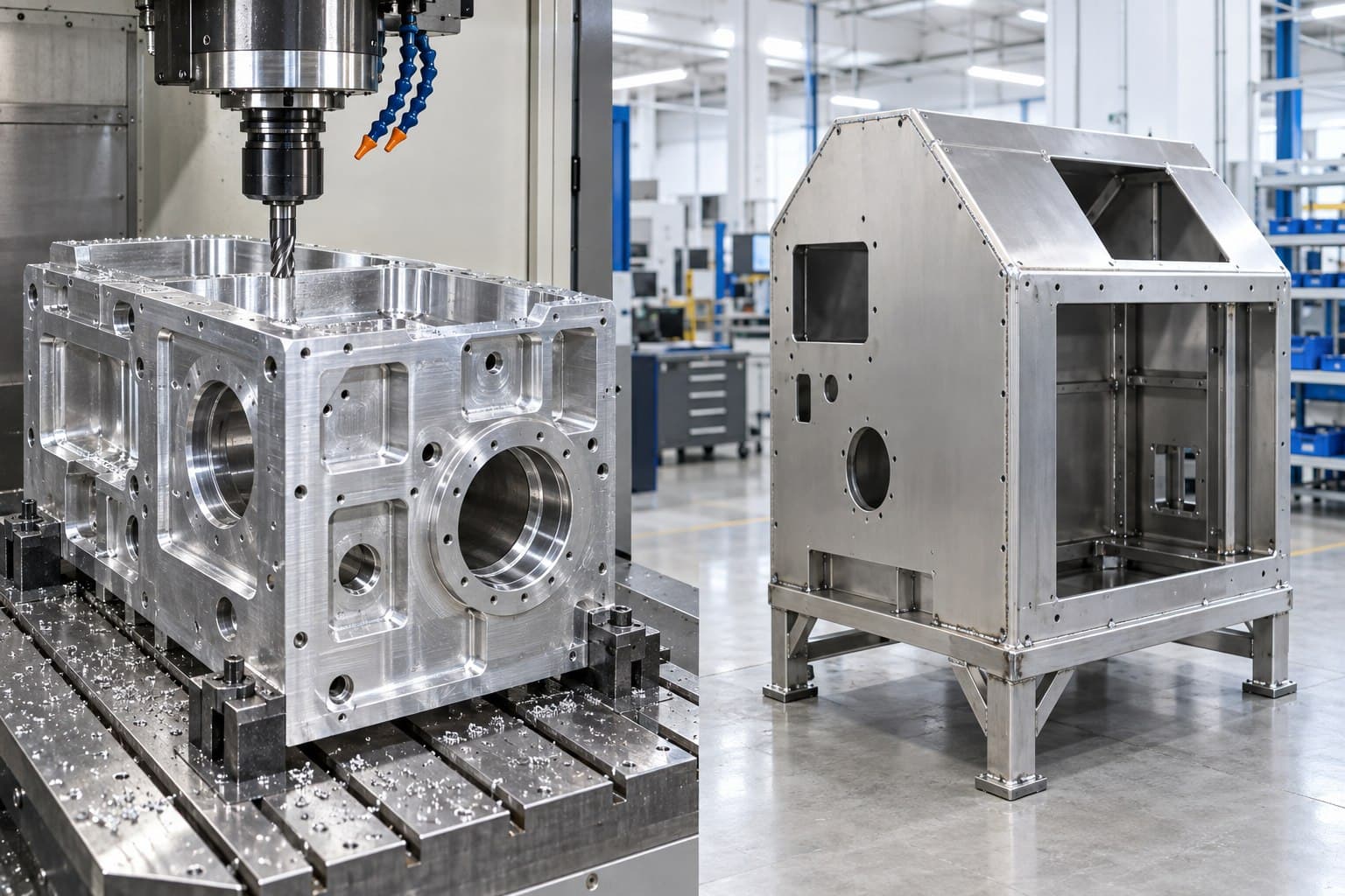
Many large parts do not need an all-machined or all-fabricated answer. A fabricated frame can provide the overall structure while CNC-machined pads, bushings, rails, bearing blocks or datum plates provide the precision interfaces. Local machining may also be performed after welding when the design requires final alignment across the completed assembly.
The hybrid route should be designed intentionally. Identify which dimensions must be achieved after joining, where machining allowance is needed, how the assembly will be supported, and whether the final interfaces can be reached by the selected equipment. A welded blank without a datum and stress-management plan can create more risk than it removes.
- Fabricated frame plus machined mounting plates
- Welded housing with post-weld machining on sealing or bearing interfaces
- Sheet-metal enclosure with machined inserts, bosses or heat-sink interfaces
- Large plate assembly with precision locating blocks and replaceable wear components
06
Tolerance and inspection change with the process
A tolerance should protect function and be connected to a realistic manufacturing and measurement method. On a large machined part, rigidity, material removal, temperature, setup transfer and support conditions can influence distant feature relationships. On a fabricated assembly, bend variation, joint fit-up, welding sequence and heat input can influence the final envelope.
Do not apply the same tight tolerance to every dimension. Define the functional datum scheme, identify the bores, faces or hole patterns that control assembly, and state whether requirements apply before or after coating, heat treatment or welding. If a feature requires a dimensional report, CMM inspection or a particular acceptance condition, include it in the RFQ rather than after the quote.
07
What to include in an RFQ for a large metal part
A useful quotation depends on the complete requirement, not only a screenshot or overall dimensions. Send the current controlled files and identify any acceptable alternatives separately so the supplier can compare process routes without guessing at the design intent.
- STEP or STP model of the finished component or complete assembly
- Controlled 2D drawing with revision, datums, critical GD&T and finish callouts
- Exact material grade, condition, sheet thickness or proposed raw-stock form
- Finished envelope, estimated or known weight and any handling limitations
- Prototype, validation and production quantities, including expected repeat demand
- Welding, installed hardware, heat treatment, coating and masking requirements
- Inspection reports, material documentation, packaging and destination requirements
- Target timing and any interfaces that must mate with existing equipment
08
A short process-selection path
Start by marking the functional interfaces on the drawing. If the design is mainly a solid body and performance depends on precise related bores, faces or thick sections, begin with a CNC machining review. If the design is mainly an enclosure, frame or open structure, begin with a sheet metal fabrication review. If the structure is large but only a few interfaces need precision, compare a hybrid fabricated-and-machined route.
The final decision should be made from the full CAD model, controlled drawing, material, quantity, inspection plan and delivery requirements. MIM Machining can review these inputs together and identify the questions that must be resolved before a process and quotation are confirmed.
Frequently asked questions
Questions engineers and buyers ask before quotation.
Is CNC machining always more accurate than sheet metal fabrication?+
No process is automatically more accurate for every feature. CNC machining is often better suited to precise bores, faces and datum relationships, while fabricated assemblies can meet their own functional requirements when bend, joint, weld and inspection controls are designed correctly. The drawing should define the critical characteristics rather than a blanket tolerance.
Is sheet metal fabrication always cheaper for a large part?+
Not always. It can use material efficiently for shells and frames, but welding, fixturing, distortion control, hardware, finishing and post-weld machining may add cost. Compare total scope and risk, not raw material alone.
Can a welded assembly be machined after fabrication?+
Yes, when access, support, machining allowance, datum strategy and material condition are planned for the completed assembly. The feasibility and sequence should be reviewed before the weldment is released.
What files are needed to compare both routes?+
Send a complete 3D model and controlled 2D drawing, plus material, quantity, critical tolerances, finish, joining, inspection, packaging and timing requirements. For a fabricated option, assembly drawings and flat patterns are also helpful when available.
How does MIM Machining confirm capacity for a large component?+
Capacity is reviewed against the actual finished geometry, raw stock, weight, fixture space, tool access, handling, process sequence and inspection method. A nominal machine envelope alone is not treated as confirmation.
Plan the next step
Continue from guide to project review.

Julie Cai
Project contact connecting international customers with MIM Machining's manufacturing and engineering review team.
Contact Julie