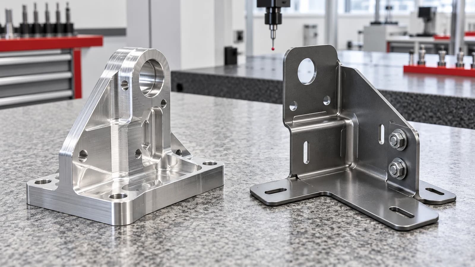
A small cut near a bend can influence the fit and appearance of the finished assembly. Reviewing relief geometry together with material, bend tooling and nearby features helps prevent avoidable drawing changes after fabrication starts.
Key takeaways
Review the ends of each bend and the corners where flanges meet.
Confirm relief dimensions against material and the proposed forming process.
Check the finished assembly, not only the flat pattern.
01
What bend relief is intended to do
Bend relief is a cut near the end of a sheet metal bend that separates the region being formed from adjacent material. It provides space for deformation where a flange ends within a larger sheet. Corner relief addresses the region where adjacent bends meet.
These features deserve attention in brackets, covers and enclosures because a local defect can affect more than appearance. Review the feature in both the flat pattern and the formed model to understand what material must remain and where movement is needed.
02
Review the bend ends before selecting a cut shape
Identify bends that stop before the edge of the blank and corners where multiple flanges converge. Review each in relation to nearby mounting holes, welds and mating faces. A relief should solve the local forming problem without creating a new opening where the assembly requires continuous material.
Do not assume that a CAD default has been checked against the actual fabrication route. Ask the supplier to confirm the proposed detail using the specified material, thickness, inside radius and tooling. Record any recommended change in the controlled drawing.
03
Why one universal relief dimension is not enough
Material behavior, thickness and the bend geometry influence the required detail. Cutting capability and the forming sequence also matter. A practical specification states the desired geometry and acceptance requirements while allowing the fabricator to flag unsuitable features before release.
Avoid adding a fixed rule to every drawing without checking its consequences. A relief that is unnecessarily large may reduce a mounting area or leave a visible gap. One that is insufficient may not provide the separation needed at the bend end.
| Input | Why it matters | Review question |
|---|---|---|
| Material and thickness | Influence forming behavior | Is the exact grade and condition defined? |
| Inside radius | Defines the formed region | Does it match the proposed tooling? |
| Relief extent | Separates adjacent material | Does it cover the intended region? |
| Nearby features | Affect fit and strength | Are holes and edges still functional? |
04
Check nearby holes and enclosure corners
Relief geometry is not a substitute for reviewing a hole placed too close to a bend. Assess whether forming could distort the hole or alter its location relative to the mating component. Where a feature is critical, discuss whether its position or manufacturing sequence needs revision.
For an enclosure, inspect the complete corner after all flanges are formed. Consider whether the resulting opening affects a gasket, weld path, cable route or cosmetic requirement. A visually neat flat pattern does not establish that the assembled corner will meet its purpose.
05
Include finishing and inspection in the review
Specify edge treatment and accessible burr removal where the relief meets a handled or assembled surface. If welding or coating follows forming, review the sequence and the areas that require protection or masking.
Agree what will be measured on the formed part: flange angle, key dimensions, hole relationships and any appearance-sensitive region. For example, a mounting bracket may need a mating check in addition to an angle measurement. Define that check before comparing supplier quotations.
06
Send a consistent fabrication package
Provide MIMCNC with the formed model, controlled drawing and any available flat pattern, together with material, thickness and quantity. State which document governs if the supplied files disagree.
Include the finish, critical interfaces and target delivery date. Ask for clarification of proposed relief changes before the drawing is released. This keeps engineering approval separate from the supplier’s manufacturing assumptions and helps the quotation reflect the finished assembly.
- Material grade, condition and thickness
- Inside bend radius and formed dimensions
- Relief and corner details
- Critical holes, mating surfaces and edge requirements
- Finish, quantity and inspection expectations
07
Image credit
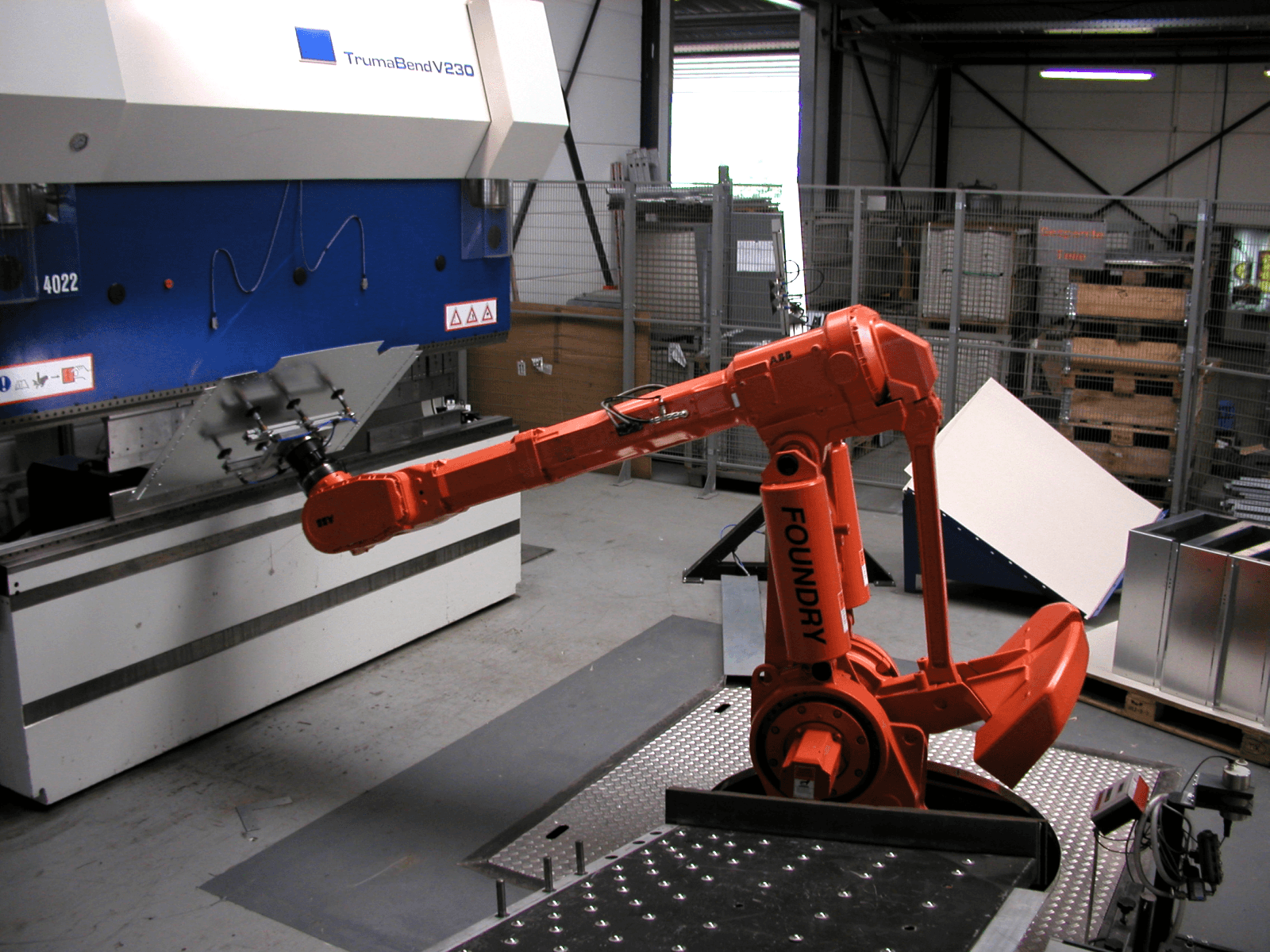
Reference photograph: Borowski, Bend press Robot, public domain. It illustrates a bending process and does not represent MIMCNC equipment or a customer project.
Frequently asked questions
Questions engineers and buyers ask before quotation.
Does every bend require relief?+
No. Review the bend ends, adjoining material and corner geometry with the fabricator.
Can relief fix a hole that is too close to a bend?+
Not by itself. Hole location, distortion risk and manufacturing sequence require separate review.
Should the flat pattern control all acceptance checks?+
No. Functional acceptance usually includes formed dimensions and assembly relationships defined by the drawing.

Julie Cai
Project contact connecting international customers with MIM Machining's manufacturing and engineering review team.
Contact Julie