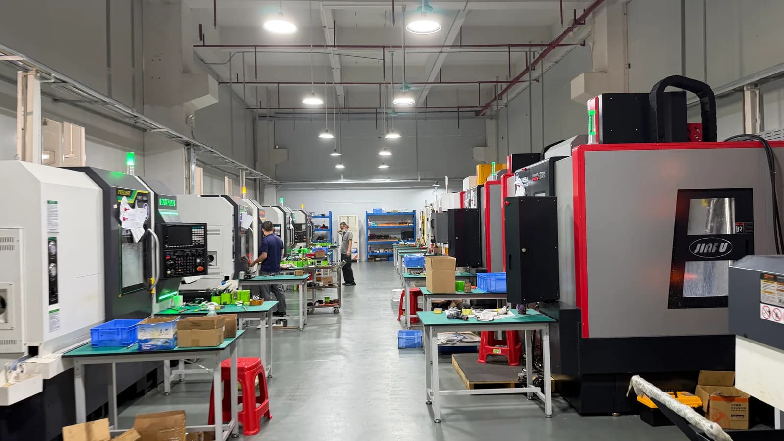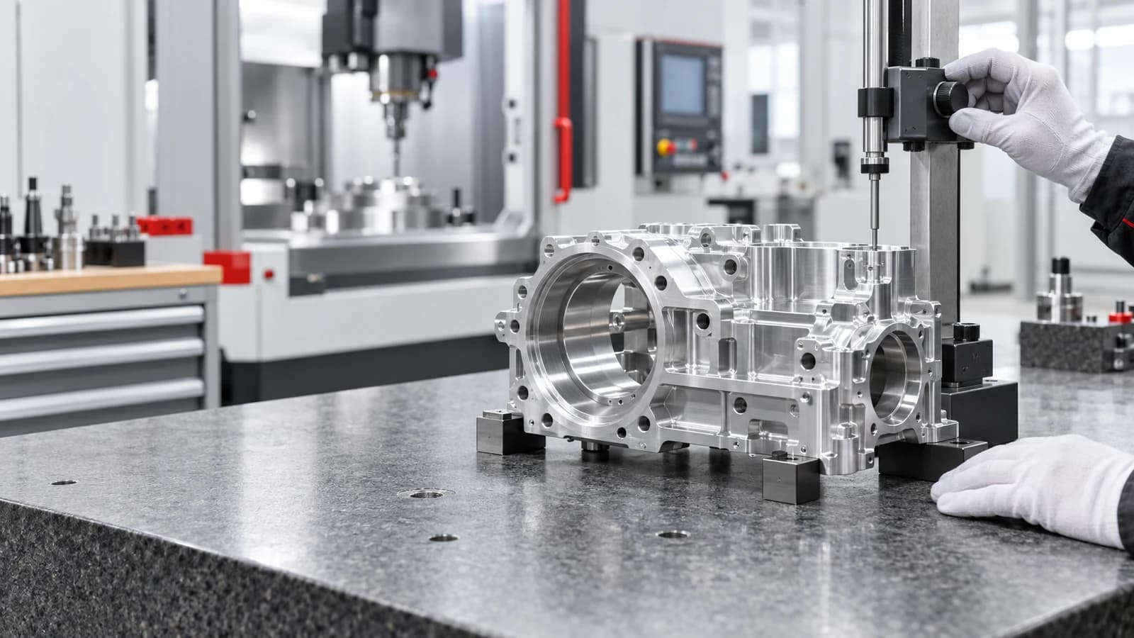
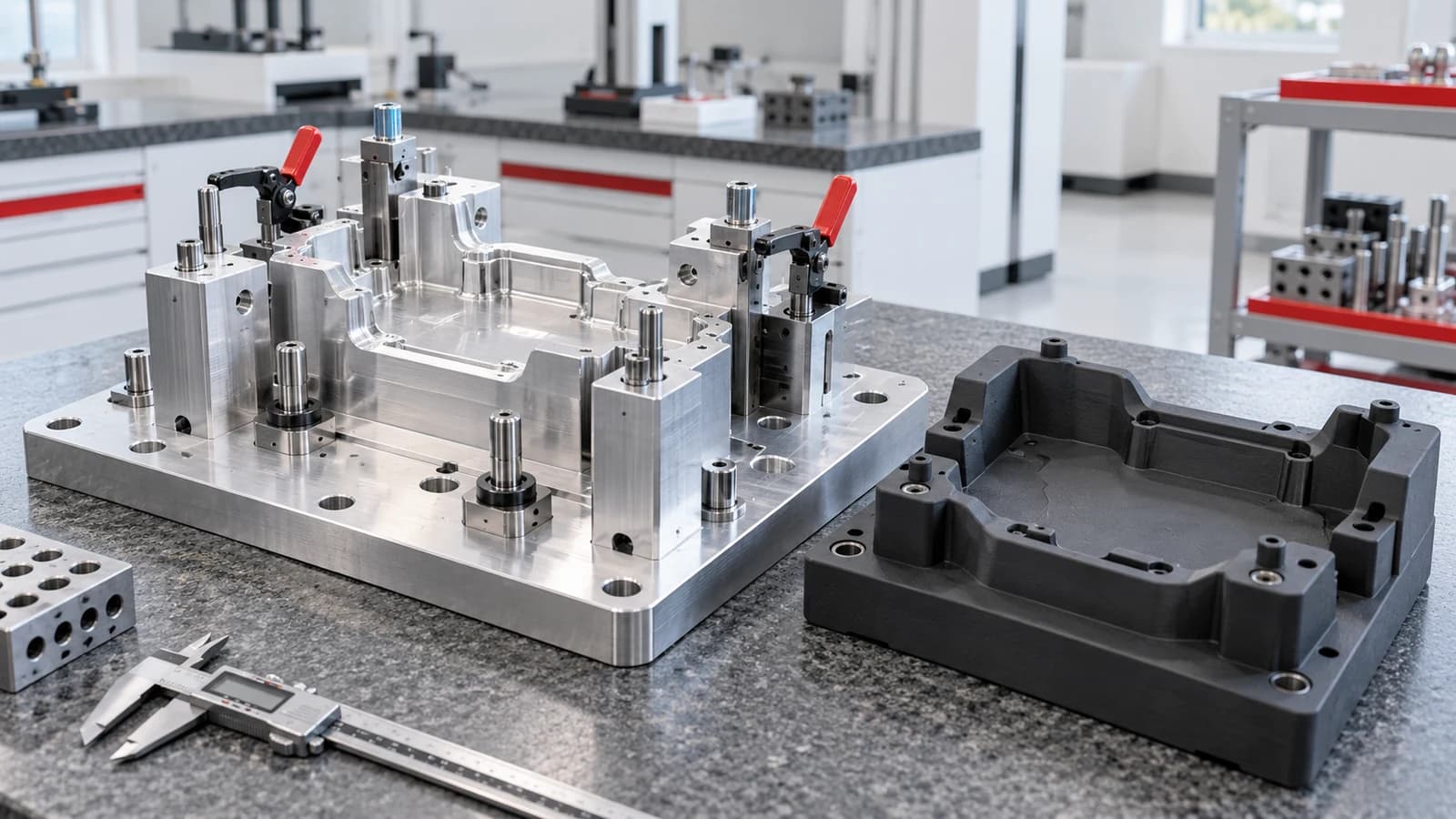
A production tool should be selected from its duty rather than from the manufacturing process that is easiest to buy. This guide compares machined metal, printed polymer and hybrid tooling for locating, clamping, guiding and inspection tasks, then turns the decision into a quote-ready specification.
Key takeaways
Choose tooling from load, temperature, wear, chemical exposure, accuracy and expected service cycles rather than from purchase price alone.
Use machined metal where datums, clamp loads, cutting forces or wear surfaces must remain stable, and consider printed tooling for light-duty, revision-sensitive or ergonomic tasks.
Define the locating scheme, replaceable wear elements, inspection method, revision control and expected quantity before requesting a tooling quotation.
01
Quick selection matrix for production tooling
A jig guides a tool or operation; a fixture locates and holds the workpiece. In practice, many production tools combine both functions with checking, poka-yoke or handling features. The correct manufacturing route depends on what the tool must resist and how its accuracy will be verified.
The table below is a screening tool, not a universal material rule. Geometry, safety, process forces, environment and validation requirements remain project-specific.
| Tooling duty | Machined metal | Printed polymer | Hybrid route | Key RFQ evidence |
|---|---|---|---|---|
| Cutting, drilling or heavy clamping | Strong candidate where rigidity and wear control are critical | Usually limited by stiffness, heat, creep or tool contact | Printed body with machined base, bushings or wear plates | Cutting force, clamp load, tool path, cycle count and safety review |
| Assembly nest or bonding fixture | Useful for stable datums, repeat programs and heat exposure | Useful for complex contours, light loads and frequent revisions | Machined datum frame with replaceable printed nests | Part contact map, cure temperature, chemicals and expected revisions |
| Inspection fixture or gauge | Useful when datum repeatability and long service life dominate | Useful for protected profiles, visual aids and low-use checking | Machined reference features with printed ergonomic body | Characteristic, tolerance, gauge method, calibration and wear plan |
| Soft jaws and protective supports | Repeatable and durable with controlled machined contact | Can protect cosmetic surfaces and accommodate complex contours | Metal carrier with replaceable printed contact pads | Clamp direction, contact pressure, finish protection and replacement interval |
| Line-side tray or orientation aid | Usually unnecessary unless load, heat or washdown demands metal | Often practical for low load and fast revision | Printed tray with metal inserts at high-wear points | Part variants, cleaning method, handling cycle and label control |
02
Define the tooling function before choosing a process
Start with the work the tool must perform. A locating nest that only orients a component has a different risk profile from a drill jig that carries hardened bushings or a machining fixture that reacts cutting force. List the locating, supporting, clamping, guiding, checking and operator-handling functions separately.
The tool should also have a controlled relationship to the workpiece revision. Identify the part number and revision it accepts, the orientation it enforces and any variants it must prevent from being loaded. A tool can be dimensionally correct and still fail in production if it allows the wrong part, traps debris on a datum or gives the operator no clear loading sequence.
- Part numbers and revisions accepted by the tool
- Operation sequence and required operator access
- Primary, secondary and tertiary locating features
- Clamp direction, load path and release method
- Guided tools, sensors, gauges or assembly hardware
- Error-proofing and wrong-part prevention requirements
03
Compare load, stiffness, creep, heat and chemical exposure
Tool stiffness matters whenever deflection changes the produced or measured feature. Machined aluminum or steel can provide a stable load path for clamp force and cutting reaction, but the section geometry, fasteners and mounting surface still control the complete system. A thin metal plate can flex, while a well-supported polymer nest may be adequate for a light assembly operation.
Printed polymers require additional attention to sustained load, temperature, layer orientation, moisture and chemical contact. A tool that survives a short proof test may gradually move under a constant clamp load or soften near a heat source. Cleaning fluids, adhesives, coolant and sterilization methods can change the material choice. Record the actual service environment instead of specifying a generic 'strong plastic.'
- Peak and sustained clamp or handling load
- Cutting, pressing, insertion or torque reaction
- Maximum service and cleaning temperature
- Coolant, solvent, adhesive and washdown exposure
- Impact, drop and operator-handling conditions
- Permitted deflection at the controlled feature
04
Build a repeatable 3-2-1 locating and clamping strategy
A fixture should remove the required degrees of freedom without forcing the part against competing locators. The familiar 3-2-1 principle provides a useful starting framework for prismatic parts: three points establish a primary plane, two establish a secondary direction and one establishes the final position. The actual scheme must suit the component, stability and functional datums.
Clamps should push the part into its locators, not pull it away or distort a flexible wall. Keep locating surfaces clear of burrs, flash, weld beads and uncontrolled cosmetic areas. Provide chip, dust or adhesive relief so contamination cannot hold the workpiece off the datum. Where the tool supports several revisions, use controlled replaceable components rather than informal shims.
05
When CNC machined jigs and fixtures are the stronger choice
CNC machined tooling is usually worth evaluating when the tool carries significant load, controls a tight feature relationship, works near heat or cutting fluid, or must survive repeat production with predictable wear. Precision CNC machining can create datum pads, bushing bores, mounting patterns, nests and replaceable details from a controlled coordinate system.
Metal is not automatically the most accurate answer. The design still needs accessible CNC mill tooling, practical internal radii, stable stock, a clear setup strategy and an inspection plan. Hardened bushings, wear strips or replaceable inserts may be more economical than making the complete fixture from a high-cost material. Separate the durable frame from consumable contact components where service conditions allow.
- Machining, drilling, pressing or high-torque assembly fixtures
- Long production programs with controlled maintenance
- Datum relationships that require measured repeatability
- Hot, abrasive, coolant-rich or washdown environments
- Tools that need threaded inserts, bushings, pins or wear plates
- Programs requiring documented dimensional inspection
06
When 3D printed tooling can reduce iteration time
Printed tooling can be useful when the primary challenge is shape rather than load: an ergonomic handling aid, a complex protective nest, a visual orientation guide or a low-use check fixture. It can also shorten the feedback loop while the product is still changing because the contact geometry can be revised without reworking a complete metal body.
Process labels alone do not establish fitness. Printed parts can be anisotropic, and their dimensional behavior, surface texture and internal quality depend on process, orientation, material and post-processing. Define which surfaces are functional, what accuracy is required and how the completed tool will be qualified. Do not treat a visually acceptable print as a released production gauge without measurement evidence.
07
Use hybrid tooling to put durability only where it is needed
Hybrid tooling can combine a machined metal base or datum frame with printed nests, protective contact pads or operator aids. Hardened drill bushings, dowel pins, threaded inserts and wear plates can be installed at concentrated load and wear points. The printed component then provides shape, low mass or rapid revision without carrying the complete duty.
The interface between materials must be designed deliberately. Control how the insert locates, how thermal expansion is accommodated, which fasteners retain it and how a replacement is verified. A replaceable component needs its own part number, revision and inspection criteria so maintenance does not change the released tool unknowingly.
08
Plan tooling inspection, approval and maintenance
Tool acceptance should connect to the product characteristic it protects. Verify datum locations, guide features, clamp clearance and functional loading rather than inspecting only convenient dimensions. An inspection fixture also needs a measurement-system review: repeat loading, operator technique, contact wear and environmental conditions can affect the result.
Establish a master record for the released tool, including drawing, CAD model, bill of materials, inspection report and approved product revision. Identify wear points and define when bushings, pads or inserts are checked or replaced. After repair, confirm the affected characteristics before returning the tool to production.
- Tool identification and released revision
- Datum and guide-feature inspection results
- Functional loading or trial-run evidence
- Approved workpiece and operation revision
- Wear checkpoints and replacement components
- Storage, corrosion protection and recalibration requirements
09
Prepare a quote-ready jig and fixture RFQ
Send the tool model together with the current workpiece model and controlled drawings. A supplier cannot confirm workholding or gauge intent from the fixture body alone. Describe the production operation, load, service environment, expected cycles and which features control acceptance. State whether the request is for a concept review, prototype tool or released production tooling.
MIM Machining reviews drawing-based custom CNC machining services for machined tooling and components. Printed or hybrid elements, materials, inserts, inspection scope and final assembly must be confirmed for the specific project. Sharing the complete use case supports a more useful DFM review than requesting a material and price without operating requirements.
- Tool CAD, controlled drawing and current revision
- Workpiece CAD, drawing and approved sample if available
- Operation description, loading sequence and cycle time context
- Loads, temperature, chemicals and expected service cycles
- Datums, critical dimensions and inspection-report scope
- Required quantity, spare inserts and maintenance expectations
- Target delivery, packaging and destination
10
Technical references
These resources support the design and qualification framework. The released workpiece drawing, tooling drawing, service environment and validated process remain controlling for each project.
11
Send your production tooling package for review
Send the fixture or jig model, workpiece drawing, expected load, service environment, quantity and inspection requirements. MIMCNC can review the machined features, material, inserts, workholding interfaces and documentation needed for a quote.
Use the inquiry page or contact Julie Cai at juliecai@mimcnc.com and +86 136 7015 0900. Tooling capability and process details are confirmed against the actual project before quotation.
Frequently asked questions
Questions engineers and buyers ask before quotation.
What is the difference between a jig and a fixture?+
A jig guides a tool or operation, while a fixture locates and holds the workpiece. Many production tools combine locating, clamping, guiding, checking and error-proofing functions, so the drawing should define the actual duty rather than rely only on the name.
When should a jig or fixture be CNC machined?+
Machined metal is usually worth evaluating when the tool carries cutting or clamp load, controls important datums, faces heat or chemicals, contains wear elements or must remain stable through repeat production. The final choice depends on geometry, material, service conditions and validation.
Can a 3D printed fixture be used for inspection?+
It can support some low-use or protected checking tasks, but the functional surfaces, dimensional behavior, wear and repeat loading must be qualified. A printed tool should not be treated as an accepted production gauge solely because it matches the CAD visually.
What is hybrid tooling?+
Hybrid tooling combines processes or materials, such as a machined datum frame with printed nests, or a printed body with metal bushings, pins and wear plates. It places rigidity and durability at critical interfaces while retaining fast revision or complex contact geometry elsewhere.
How should a machining fixture be inspected?+
Inspect the datum scheme, guide features, clamp clearances and the relationships that protect the workpiece. Functional loading or a trial run may also be needed. Record the released revision, approved workpiece and maintenance checkpoints.
What files are needed for a jig or fixture quotation?+
Provide the tooling CAD and drawing, workpiece CAD and drawing, operation sequence, loads, temperature and chemical exposure, expected service cycles, quantities, critical dimensions, inserts, inspection requirements and target delivery.
Plan the next step
Continue from guide to project review.

Julie Cai
Project contact connecting international customers with MIM Machining's manufacturing and engineering review team.
Contact Julie