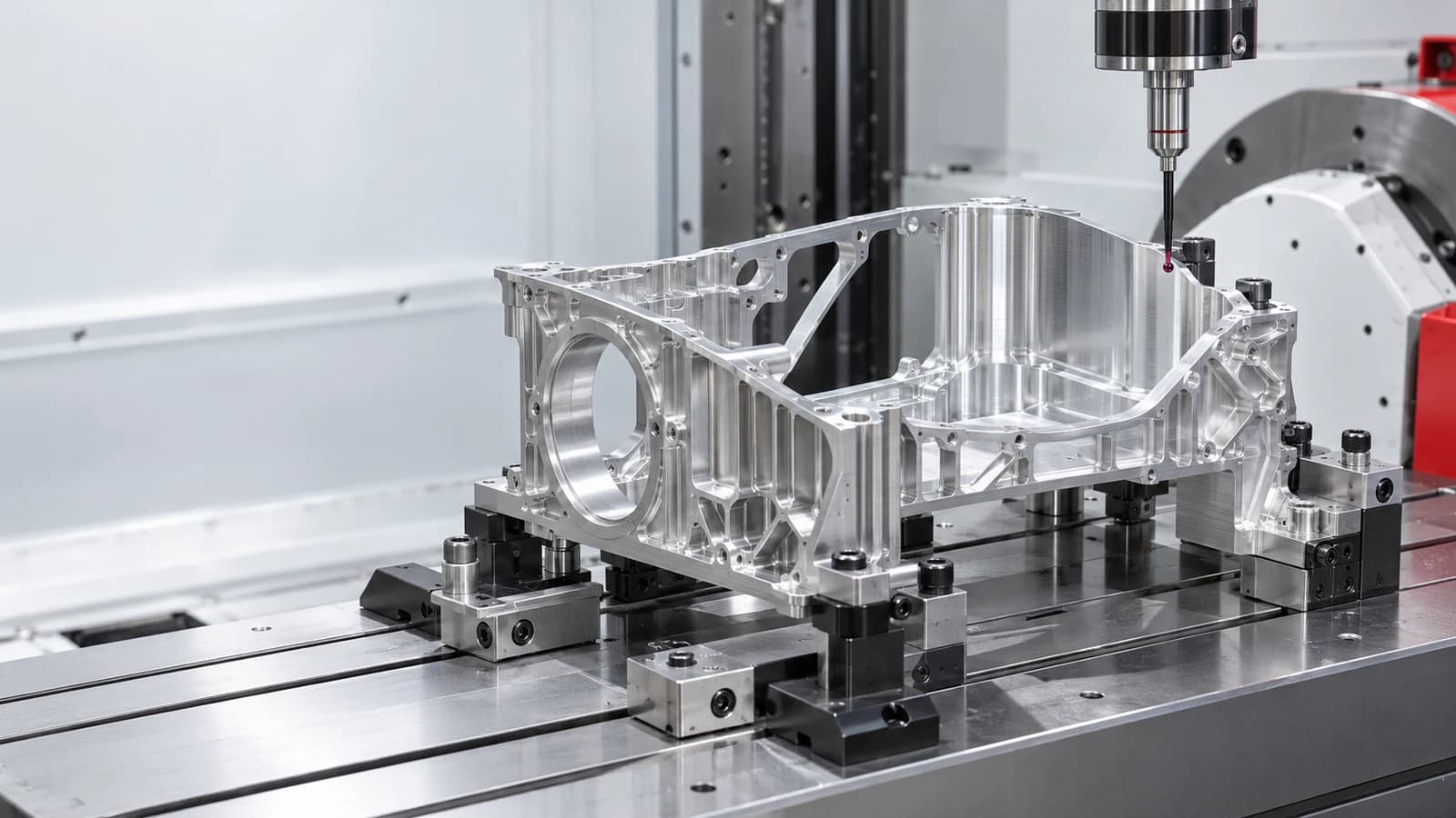
Thin-wall CNC machining is a stiffness and process-control problem, not a single minimum-thickness number. Wall height, unsupported span, material, stock condition, tool engagement, clamping and measurement state determine whether a lightweight housing or enclosure can be machined and inspected consistently.
Key takeaways
Do not specify thin walls from one generic minimum: evaluate wall height, unsupported span, material, stock condition, access, quantity and functional tolerance together.
Preserve stiffness through design, workholding and machining sequence, then define whether final inspection applies in a free or restrained state.
Send the supplier the complete drawing, CAD model, wall-critical features, quantities, finish and inspection requirements before the process route is confirmed.
01
Quick answer: thin-wall machining depends on stiffness, not thickness alone
A wall becomes difficult to machine when cutting, clamping, thermal or residual-stress forces are large compared with the local stiffness of the feature. A short supported rib can remain stable at a thickness that would deflect badly as a tall enclosure wall. The surrounding geometry, open edges, pockets, transitions and order of material removal therefore matter as much as the nominal wall value.
For design and quotation, show the wall thickness together with unsupported height and length, adjacent ribs, floor thickness, internal radii, material condition, removed volume and functional tolerances. Ask for CNC machining DFM analysis on the complete model rather than relying on a universal online minimum.
| Risk area | Why it matters | What to provide | What the process review should address |
|---|---|---|---|
| Wall height and span | Deflection rises as unsupported geometry becomes more flexible | Wall thickness, height, length, ribs and open edges | Support strategy, cutting direction, finish allowance and measurement state |
| Material and stock | Residual stress and thermal behavior influence movement after material removal | Grade, temper, product form and certificate requirement | Stock selection, roughing balance and any permitted stabilization route |
| Workholding | Local clamp force can distort the part or hide free-state error | Surfaces allowed for contact, clamp and marking | Load distribution, soft jaws, nests, sacrificial features or alternative support |
| Tool access | Long overhang and deep engagement reduce rigidity and chip evacuation | Pocket depth, radii, undercuts and restricted faces | Tool length, setup count, cutter access and chip-control plan |
| Tolerance | Flexible geometry may change between cutting, release and measurement | Functional datums, profile, flatness, wall and interface requirements | Free or restrained inspection, sampling and reporting method |
| Quantity | Fixtures and process development are distributed differently across prototypes and repeat batches | Prototype, validation and production quantity breaks | Flexible prototype workholding versus dedicated repeat-production control |
02
Why thin walls deflect, vibrate and move after machining
Cutting force can push a flexible wall away from the tool. The wall may spring back after the cutter passes, producing taper, thickness variation or a surface pattern even when the program is correct. Dynamic interaction between tool, holder, spindle, workpiece and fixture can also create chatter. A short rigid tool helps, but the system remains limited by the least-stiff element.
Material removal changes the stress balance in the stock. Rolled, extruded, forged and cast products can contain residual stress from their manufacturing history. Removing a large volume from one side or creating a thin asymmetric shell may allow the remaining material to move. Clamping can add elastic strain, and cutting heat can temporarily change size or shape. These effects can combine, so thin-wall CNC machining requires a planned sequence rather than one parameter adjustment.
03
Design geometry that preserves stiffness where function allows
The most effective process improvement may be a small design change made before release. If weight permits, increase wall thickness locally at unsupported regions, sealing interfaces, bosses and transitions. Ribs, flanges and closed sections can improve stiffness without thickening every surface. Their dimensions should follow load, molding or machining needs rather than a copied ratio from another process.
Avoid abrupt wall changes that concentrate stiffness and leave a flexible transition. Add internal radii that suit available cutters and reduce sudden engagement changes. Provide access for a suitably rigid tool instead of forcing a long small-diameter cutter into a deep cavity. If an external surface must remain cosmetic, identify where temporary support, tabs or fixture contact are permitted.
- Show nominal wall thickness and any allowed local reinforcement
- Use ribs, beads, flanges or closed geometry where the load path supports them
- Blend wall and floor transitions with practical radii
- Avoid unnecessary deep narrow pockets beside flexible walls
- Provide stable datum and clamping regions
- Identify faces that cannot carry witness marks or temporary support
04
Select material and stock condition for dimensional stability
Aluminum CNC machining is common for lightweight housings and frames, but the full callout matters. Alloy, temper, product form, thickness and supplier condition affect strength, machinability and residual stress. Stress-relieved plate may behave differently from ordinary plate or extrusion. Stainless steel, titanium, copper alloys and engineering plastics introduce different cutting-force, heat and relaxation behavior.
Do not substitute material solely to make machining easier without checking design performance, corrosion, temperature, joining and finishing. When flatness or profile is critical after large stock removal, discuss stock condition and permitted thermal or mechanical treatments before quotation. Any treatment must remain compatible with the required final material properties and documentation.
05
Plan roughing, support and finishing as one sequence
A stable route usually preserves support for as long as practical. Roughing can leave stock on walls and floors while most material is removed. The part may then be released, relocated or allowed to stabilize before semi-finishing and final passes. Symmetric or alternating removal can reduce one-sided stress release on suitable geometry, but the sequence must also protect datums and workholding surfaces.
Finish allowance should be large enough to remove roughing effects but not so large that the finishing cut pushes the wall. Entry, exit and corner engagement should be controlled to avoid sudden load changes. The process plan should state which features are created in the same setup and when the final datum surfaces are established. For multi-face housings, 5-axis CNC machining services may reduce repositioning or improve tool orientation, but only if the geometry, fixture and critical relationships justify that route.
06
Control tool rigidity, engagement, heat and chip evacuation
Tool overhang, diameter, holder connection and spindle condition influence deflection and vibration. Use the shortest practical assembly and a cutter suited to the material and feature. Radial and axial engagement, feed, speed and toolpath should keep cutting load predictable rather than repeatedly shocking the wall. The correct values depend on the cutter, material, machine, engagement and coolant strategy; universal parameter tables cannot replace supplier data and process validation.
Chips trapped between the cutter and workpiece can mark the surface, add heat and accelerate tool wear. Deep pockets and internal corners require a deliberate evacuation route. Coolant or air strategy must suit the material and downstream cleanliness requirements. For temperature-sensitive plastics, heat control is especially important because both the workpiece and measurement result may change with temperature.
07
Choose workholding that supports without over-constraining
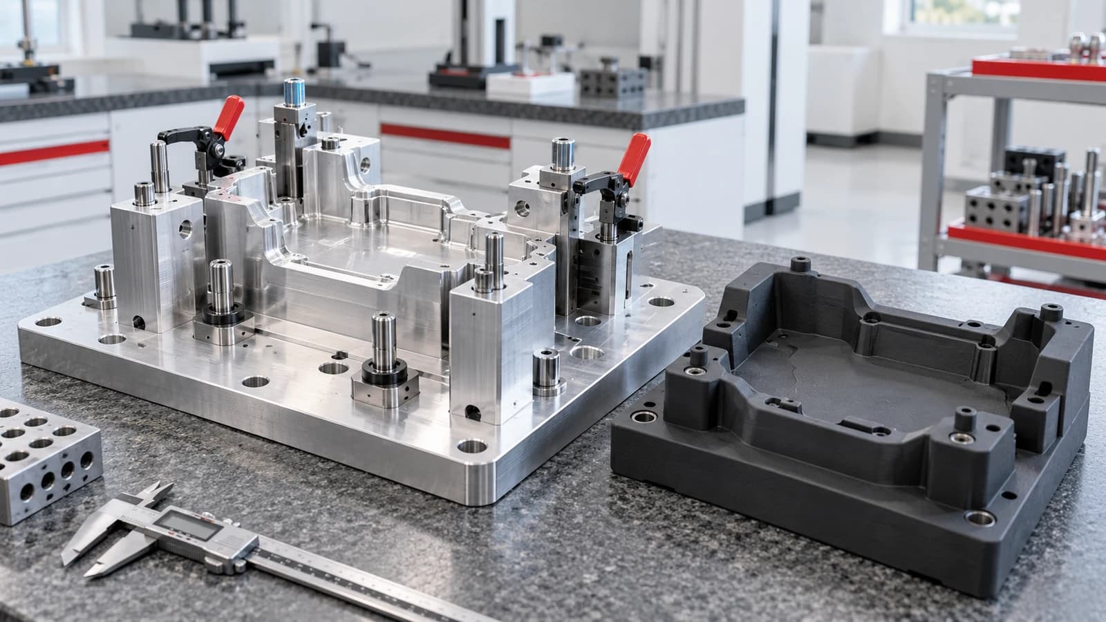
A rigid fixture can still produce a distorted part if clamp force bends the wall against the locator. Spread load over stable regions and keep contact away from unsupported cosmetic or sealing surfaces. Machined soft jaws, contour nests, vacuum fixtures, low-profile supports, temporary tabs or sacrificial material may be considered depending on the part. Each method has limits in cutting load, sealing area, access and repeatability.
Define clamp sequence and torque where variation matters. Keep locating surfaces clean and protect them from burrs and chips. If the part changes shape when released, a measurement taken only in the fixture does not describe the delivered free state. Conversely, some assemblies intentionally restrain a flexible component; the drawing must state when a restrained inspection condition represents function.
08
Specify tolerances and inspection state for flexible parts
Tight tolerance CNC machining should focus on functional interfaces rather than every point on a flexible wall. Define datums that can be produced and measured, then apply profile, flatness, position or size controls to the regions that protect assembly. If a wall is expected to flex without affecting function, a broad blanket tolerance may create cost without improving the product.
Agree whether the part is inspected in a free state, supported on datum simulators or restrained in a functional fixture. Record the support points and clamp condition if they are part of acceptance. A CMM can evaluate profiles and feature relationships, but scanning force, point strategy, alignment and fixturing must suit the component. Consider wall-thickness measurement, optical inspection, dedicated gauges or functional assembly checks where appropriate.
- Functional datum reference frame and stable measurement surfaces
- Free-state or restrained-state acceptance condition
- Critical wall thickness, profile, flatness and interface relationships
- Inspection method, sampling and report format
- Conditioning time or temperature where material response matters
- Requirements before and after heat treatment or surface finishing
09
Balance weight, manufacturability and total project cost
Thin walls can reduce weight and material, but they may add fixture design, conservative cutting, intermediate handling, inspection and yield risk. Prototype quantities often use adaptable workholding; repeat production may justify a dedicated nest or fixture and defined process checkpoints. Ask for realistic quantity breaks so the supplier can evaluate both stages.
Before locking the design, compare a small thickness increase, a local rib or a revised pocket with the manufacturing cost and product impact. Do not assume that the lightest CAD model produces the lowest delivered cost. The best design meets mass and performance targets with a process that can be repeated and inspected.
10
Send a quote-ready thin-wall CNC machining package
Provide the current 3D model and controlled 2D drawing. Highlight the thin-wall regions and explain their function, permitted movement and assembly condition. State the exact material, stock condition, quantity, finish and inspection evidence instead of asking only whether the shop can machine a particular minimum thickness.
MIM Machining reviews precision CNC machining projects against the actual geometry and drawing package. Feasibility, workholding, sequence, tolerance and inspection scope are confirmed per project; no general wall-thickness number can guarantee the result for every size, material and unsupported span.
- STEP model and controlled 2D drawing with revision
- Wall thickness, height, unsupported span, ribs and floor geometry
- Exact material grade, temper, product form and certificates
- Functional datums, critical interfaces, profile and flatness requirements
- Allowed fixture-contact, support, tab and cosmetic zones
- Prototype, validation and production quantity breaks
- Finishing, heat treatment, cleaning, inspection and packaging scope
11
Technical references
Primary machining and measurement resources support the principles in this guide. Toolmaker guidance, material data and a validated part-specific process remain controlling.
12
Send your thin-wall part for engineering review
MIMCNC supports drawing-based CNC milling, turning and multi-axis machining for custom lightweight components. Send the latest 2D drawing and STEP file with material, quantities, wall-critical features, surface finish and inspection requirements. The team can review the geometry, workholding and measurement questions before quotation.
Use the inquiry page or contact Julie Cai at juliecai@mimcnc.com and +86 136 7015 0900. Process feasibility and delivery expectations are confirmed for each project.
Frequently asked questions
Questions engineers and buyers ask before quotation.
What is considered a thin wall in CNC machining?+
There is no universal thickness that defines every thin wall. The practical risk depends on thickness relative to unsupported height and length, material stiffness, surrounding geometry, workholding, tool access, quantity and tolerance requirements.
Why do thin-wall CNC parts warp after machining?+
Residual stress can redistribute as stock is removed, clamp force can hold the part in a strained condition and cutting heat can change geometry temporarily. Unbalanced removal and low remaining stiffness make those effects more visible after release.
Which aluminum is best for thin-wall CNC machining?+
The answer depends on strength, corrosion, joining, stock form and dimensional requirements. Stress-relieved plate may be useful for some housing geometries, but the complete alloy, temper, product form and governing specification should be reviewed rather than selecting by alloy number alone.
Can 5-axis machining improve a thin-wall part?+
It can reduce repositioning, improve tool orientation or allow shorter tool reach on suitable geometry. It does not eliminate material stress, wall deflection, fixture distortion or the need for an inspection plan.
How should a flexible machined part be inspected?+
The drawing and quality plan should define whether acceptance is in a free state, on datum supports or restrained in a functional fixture. Select CMM, contact, optical, thickness or functional methods that suit the feature and document the support condition.
What information is needed for a thin-wall CNC machining quote?+
Provide the STEP model, controlled drawing, exact material and condition, thin-wall geometry, functional datums, tolerances, permitted fixture contact, quantities, finish, inspection records and delivery requirements.
Plan the next step
Continue from guide to project review.

Julie Cai
Project contact connecting international customers with MIM Machining's manufacturing and engineering review team.
Contact Julie